Alignment
In a ZEN Connect project, you can manually align images in your workspace to correct their position or size with respect to the samples. To do so, you activate the alignment process and start aligning image data. Within a ZEN Connect project, you can also calibrate your system using a sample holder with fiducial markers by moving between the markers and confirming their positions.
Activating the Alignment Process
The alignment process lets you align your current session with fiducial marks or previous images. You can align image data manually.
You should create a new session any time the alignment of the sample in the microscope has been disturbed.
- A ZEN Connect project is loaded.
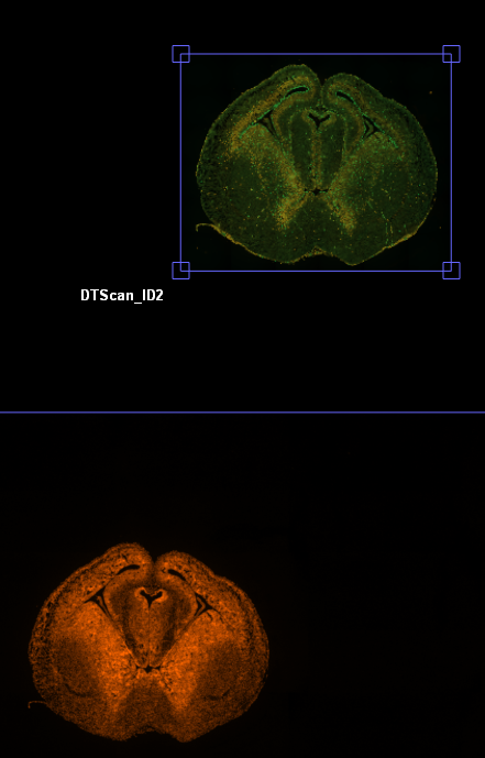
- In the Layer View, or in the Project View, select the image you want to align. Alternatively, you can select a region to select a couple of images.
- The image is marked with a square in each frame corner.

- As long as the alignment process is not activated, this is indicated with a little lock next to the cursor.
- Right-click the selected image and select Align Data.
Alternatively, right-click the image(s) in the ZEN Connect tool and select Align Data. You can also select Align for the Alignment button and click it.
- You have activated the alignment process for one or more images. The Alignment Tab below the Image View is displayed.
- You can start aligning image data. If you start an alignment on a session node, the set alignment is used for all current and future images of the session. You can use this if you change your sample between different systems and want to align their coordinate systems to each other.
See also
Aligning Image Data
In the alignment process, you have various options to align image data. Note that you can change the alignment mode during the alignment process. The alignment edits you have made are preserved, but you have to restart the pinning process if you have inserted any pins before changing the mode.
Note: The alignment process can be executed multiple times. Each time you run the alignment process, the end result of the last alignment is used as the starting point for the new alignment. If the initial image was far out of alignment at the start, it is easiest to do the alignment process once roughly, and then do the alignment process a second time with more precision. The second alignment will use the first alignment as a starting point, and will allow you to establish a more precise alignment quickly.
- You have loaded a ZEN Connect project and activated the alignment process.
- In the Alignment tab, select one of the following alignment modes and the region you want to align.
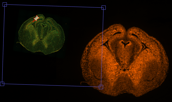
Translate Only
- Click and drag with the mouse to translate the image you are aligning with respect to everything else.
- You can zoom in and out with the mouse wheel, or press and hold the CTRL key to pan while you are in the process of aligning the image.
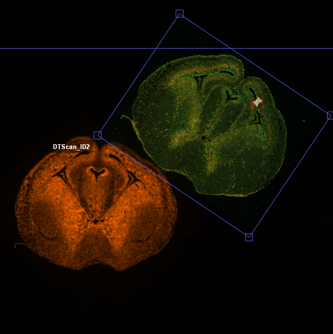
Translate and Rotate Only
- Right-click at the location you have lined up to insert the first pin, a red and grey pin icon. The pin locks the image to the reference at this location. Press the DEL key to remove the last pin you inserted.
- After you insert the first pin, your input will rotate the item around the first pin, when dragging it with the mouse.
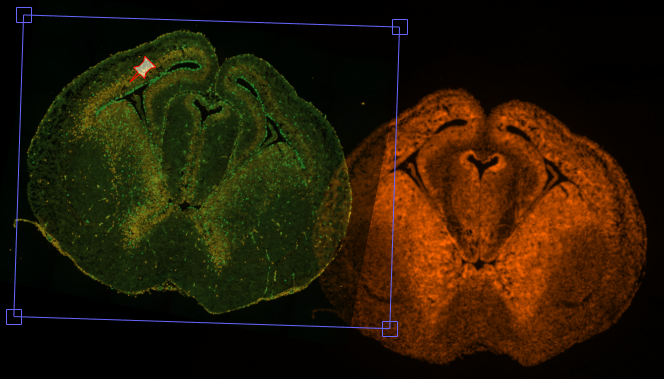
Translate, Rotate and Scale Only
- If one of the images is smaller than the other, you can scale it. Right-click to insert a pin, and drag with the mouse to scale and rotate the image.
Translate, Rotate, Scale and Shear
- Right-click to insert a second pin, and drag with the mouse to shear the image.
- After you insert the second pin, your input will also stretch and shear the item.
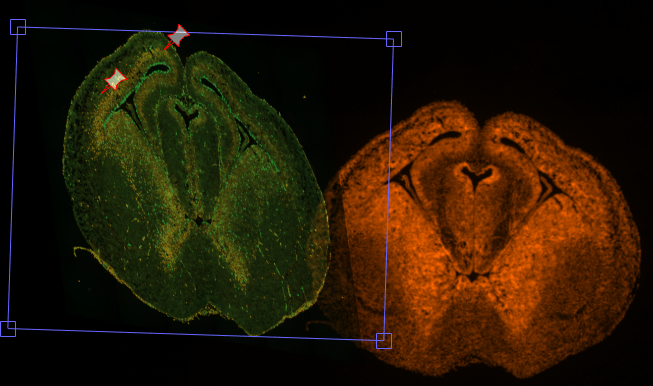
Image data from microscopes should not need to be stretched or sheared to perform alignment. If you need to provide much input after inserting the second pin, this might be an indication of other problems, such as equipment calibration issues.
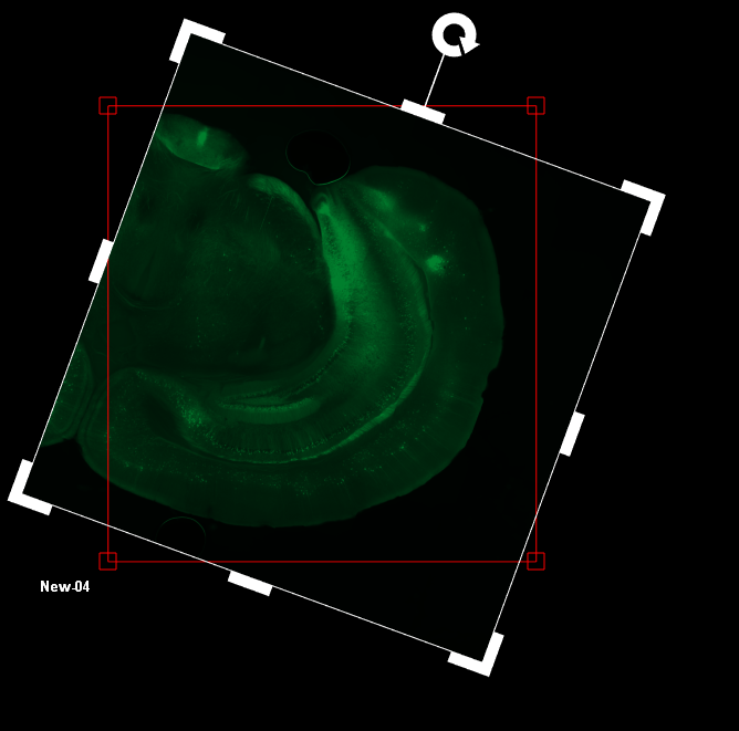
Alignment Handles
- If you select Alignment Handles, you can use handles to rotate, translate, and scale the image.
Flipping the image horizontally and vertically
You can flip your image, to mirror it.
- To flip the image horizontally, click on the Flip Horizontally button
 .
. - To flip the image vertically, click on the Flip Vertically button
 .
. - To flip the image stack in z direction, click on the Flip in Z button
 .
.
Reset alignment
- Click on the Reset button to reset the alignment you performed.
- The alignment is reverted as it was when you started aligning. The alignment mode is still activated.
Cancel alignment
- Click on the Cancel button to reset the alignment you performed.
- The current alignment is cancelled and reverted to the alignment in place before you started the alignment mode. The alignment mode is not activated any longer.
Finish alignment
- Click on the Finish button to finish the alignment mode and to save the alignment information.
Clear alignment
- Click on the Clear button.
- The session is restored to its un-aligned state.
See also
Rotating a Z-Stack
In the alignment mode you can also perform a three dimensional rotation of a z-stack.
- You have opened a ZEN Connect project.
- Select the z-stack you want to rotate.
- In the ZEN Connect tool, click on Align. Alternatively, right-click the image and select Align Data.
- The Alignment Tab below the Image View is displayed.
- For Alignment Mode, select 3D Alignment.
- Activate the checkbox Apply 3D Rotation.
- The Manipulation Controls for rotation are activated.
- Use the respective sliders or input fields to rotate the z-stack around the x, y, or z axis. Alternatively, you can use the View Cube Control to rotate the stack interactively.
- Click on Finish.
- You have now rotated the selected z-stack around the respective axis.
Aligning Images in the ZEN Connect 3D View
With the ZEN Connect 3D view you can display and align two z-stacks as 3D volumes. This alignment mode allows a translation of the volumes in x, y and z.
- You have opened two z-stack images in the ZEN Connect 3D view or directly in 3D alignment mode, see Opening Images in the ZEN Connect 3D View.
- In the Connect 3D tab, click the button for the volume you want to align, e.g. Align Volume 1. If you opened the 3D view directly in alignment mode, one volume is already selected for alignment.
- You are in alignment mode and the Alignment tab is displayed.
- To mirror the selected image, go to the Alignment tab and click to mirror the image horizontally, or click to mirror it vertically.
- In one of the 2D image views, shift the volume via drag and drop and align it with the second volume as reference.
- The changes are automatically updated in all views, including the 3D view.
- If you are satisfied with your alignment, go to the Alignment tab and click Apply.
- Your alignment changes are saved in the ZEN Connect project.
Aligning Non Image Data
- You have opened a ZEN Connect project with non-image data.
- Your non image data is toggled visible, see also Moving or Hiding Images.
- In the ZEN Connect tool or in the image view, right-click the non-image data and select Align Point Position. Alternatively, in the ZEN Connect tool, select the non-image data and select Align for the Alignment button and click it.
- You enter the alignment mode.
- In the image area, click at the position where you want to place the none-image data.
- Click on Finish.
- You have aligned your non image data.
See also
Aligning Images in the Manual Alignment Wizard
- You have opened a ZEN Connect project.
- In the correlative workspace or in the ZEN Connect tool, select the image(s) you want to align.
- In the ZEN Connect tool, for the Alignment button, select Manual Alignment Wizard and click on it.
- The ZEN Connect Alignment Wizard opens.
- To translate the selected image(s), set the distance in x and y direction with the Translate parameter section on the left.
- The translation is immediately displayed in the Image View.
- To scale the image, set the scaling factor in x and y in the Scale section.
- The scaling is adjusted according to the input.
- To rotate the image, first select the Rotation Center and then enter an Angle. The current rotation center is represented in the image by a pin.
- The selected image(s) is/are rotated.
- To flip/mirror the image horizontally, click on .
- To flip/mirror the image vertically, click on .
- If you want to shear your image, activate Enable.
- Additional shearing pins are displayed in the image. The two pins that form the "baseline" for shearing a connected by a line.
- Use the two pins to position the baseline and then move the pinpoint to shear the image.
- Click on Finish to save the alignment and close the wizard.
- You have aligned the selected image(s) in the ZEN Connect project.
Alignment Handles
You can also use the alignment manages of the selected image(s) to translate, scale, and rotate the image.
View Options
You can use the available options of the Dimensions tab to adjust the image view (e.g. use the Global-Z slider). The image which is adjusted by the Dimensions tab can be selected in the tree view of the Select Node For Dimensions tab.
Aligning Images in the Point Alignment Wizard
- You have opened a ZEN Connect project.
- In the correlative workspace or in the ZEN Connect tool, select the image(s) you want to align.
- In the ZEN Connect tool, for the Alignment button, select Point Alignment Wizard and click on it.
- The ZEN Connect Point Alignment Wizard opens.
- In the list on the left, use the
 button to add as many points as necessary for your point alignment.
With one point only a translation operation is possible, with two translation and rotation, and three or more points enable all transformations. - In the Algorithm dropdown list, select the alignment operations you want to perform.
- Click on Draw for the first point.
- You enter the drawing mode for the first point.
- In the Image Window on the left, click to set the point in your image(s) (Subject point).
- In the Project Window on the right, click to set the corresponding location for this point in the project (Reference point).
- Both color makers in the table are green and the first point for the alignment is set successfully.
- Repeat these three steps for every point you add/need.
- If you want to redraw a point pair, click on Redraw and click to set the new positions in both windows.
- Click on Next.
- The second step of the wizard opens. It displays a preview of the final alignment result and values for the parameter changes.
- If you want to change the alignment, click on Back to get back to the previous step. Otherwise, click on Finish to save the alignment and close the wizard.
- You have aligned the selected image(s) in the ZEN Connect project.
Aligning Images in the 3D Point Alignment Wizard
- You have opened a ZEN Connect project.
- In the correlative workspace or in the ZEN Connect tool, select the image(s) you want to align.
- In the ZEN Connect tool, for the Alignment button, select Point Alignment 3D Wizard and click on it.
- The ZEN Connect 3D Point Alignment Wizard opens.
- In the left image window (Tomo3D view), select the 2D image view you want to use from the dropdown as points for alignment can only be set in the 2D views.
- In the list on the left, click to add as many points as necessary for your point alignment.
With one point only a translation operation is possible, with two translation and rotation, and four or more points enable all transformations. - In the Algorithm dropdown list, select the alignment operations you want to perform.
- Click Draw for the first point.
- You enter the drawing mode for the first point.
- In the Image Window on the left, click to set the point in your image(s) (Subject point).
- In the Project Window on the right, click to set the corresponding location for this point in the project (Reference point).
- Both color makers in the table are green and the first point for the alignment is set successfully.
- Repeat these steps for every point you add/need.
- If necessary, use the controls in the Dimensions tabs, e.g. to switch to a different z-slice to set the points on specific z-levels.
- If necessary, change the left image view via the dropdown to add or check points in other 2D image dimensions.
- The view changes to the selected 2D image dimensions.
- If you want to redraw a point pair, click Redraw and click to set the new positions in both windows.
- Click Next.
- The second step of the wizard opens. It displays a preview of the final alignment result and values for the parameter changes.
- If you want to change the alignment, click Back to get back to the previous step. Otherwise, click Finish to save the alignment and close the wizard.
- You have aligned the selected image(s) in the ZEN Connect project.