Customizing the Application
Selecting Screen Design
In the upper right corner of the program window under Design, you can select a Light or Dark screen layout. Optionally, you can change the design with the shortcut Ctrl+D.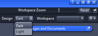
Customizing Toolbar
- You are in the Tools menu > Customize Application dialog.
- The Toolbar tab is selected by default.
- Click on an entry in the Available Toolbar Items list.
- You will see a list of all available items in this group.
- Double-click on an item.
- The item will be added to the Selected Toolbar Items list and does appear in the Toolbar within the application. Alternatively, you can add the items per Drag&Drop.
- In order to change the order of symbols in the toolbar use the Up/Down buttons.
- If you want to delete an Icon from the toolbar, click on the
 Delete button.
 - Click on Close button to close the dialog. The changes will be effective right now.
- You have successfully customized the Toolbar.
Adjusting Workspace Zoom
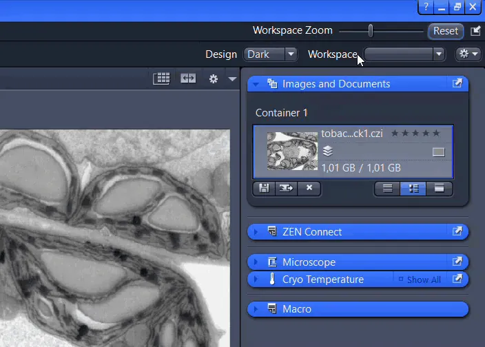
To enlarge the workspace, move the slider left or right. Click Reset to come back to the default setting.
Showing/Hiding Workspace Areas
- Click Show/Hide to show or hide screen areas.
Undocking/Docking Tool Windows
This function allows you to undock/dock a tool window. An undocked tool window can be positioned anywhere on the screen.
- Click Undock to undock a tool window. Once undocked, the tool window can be moved around by clicking and dragging it on the blue bar.
- Click Dock to dock a tool window back to its place in the left tool area.
With the dock all tools function in the Workspace Configuration you can globally attach all undocked tool windows back to their initial position.
Displaying and Adapting a Grid in the Image Area
Persistence of the Grid
If you add the grid during a Live or Continuous acquisition, the grid setting is persisted for all future acquisitions. To deactivate the grid, it has to be deactivated in the same mode as it had been activated, i.e. during Live or Continuous acquisition.
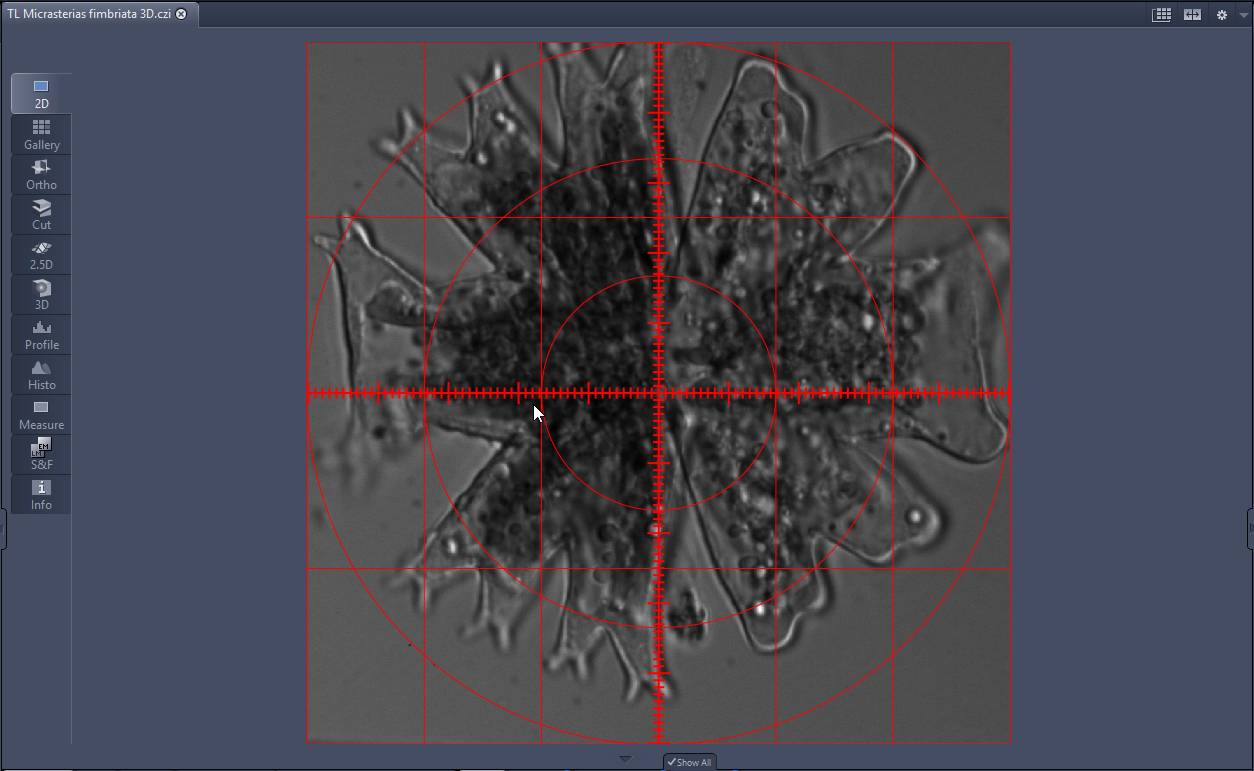
- You have opened an image in which you want to display a grid, or you have started a Live or Continuous acquisition.
- Right-click into the image and select Grid. Alternatively, click Graphics > Grid in the menu bar.
- The grid is displayed in the image.
- Right-click precisely on a grid line and select Format Graphical Elements.
- The Format Grid dialog is displayed.
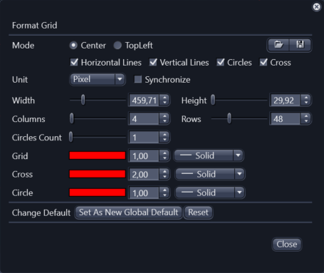
- Use the available options to adapt the grid to your needs.
- The changes are displayed in the image.
- Activate Synchronize. This function means that any changes made, e.g. to the number of columns, are adopted simultaneously for the number of rows. The grid therefore remains square.
- To set a higher number of columns, use the Columns or enter a value in the input field.
- Click
 to save the grid settings.
 - The Windows file browser opens.
- Enter a name and click Save.
- Click Close to exit the Format Grid dialog.
- You have inserted a grid into your image, edited the grid and saved your grid settings.