Aligning Images in Z Direction
In ZEN Connect you can not only align your images/ sessions in x and y direction, but also in z.
- You have opened a ZEN Connect project containing images/ z-stacks with z information.
- Select the image or session you want to shift in z direction.
- In the ZEN Connect tool, select Align for the Alignment button and click it. Alternatively, right click on the image and select Align Data.
- The Alignment Tab is displayed below the Image View.
- For Alignment Mode select 3D Alignment in the dropdown list.
- For Relative Z Offset set the value for your shift in z direction.
- Click on Finish.
- You have now aligned your data in z direction. For an illustration of the alignment see Example for Z Alignment.
Note that for the z alignment the view of the aligned stack remains the same, whereas the view of the other stacks changes.
Setting an image to the current Global Z
You can also set the center of a z-stack to the currently selected z-position of the Global-Z slider.
- You have opened a ZEN Connect project containing images/ z-stacks with z information.
- Activate the Global-Z slider and move to the z-position where you want your image to be placed.
- Select the image you want to shift in z direction.
- In the ZEN Connect tool, select Align for the Alignment button and click it. Alternatively, right click on the image and select Align Data.
- The Alignment Tab is displayed below the Image View.
- For Alignment Mode select 3D Alignment in the dropdown list.
- On the Alignment tab, click on the Set to current Global-Z button.
- Click on Finish.
- You have now set the center of your z-stack to the currently selected Global-Z.
Example for Z Alignment
This chapter serves as an illustration of how and what is happening for z alignment in ZEN Connect. Consider the following situation:
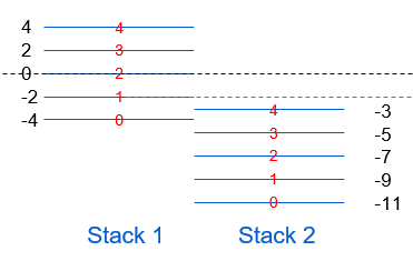
This image illustrates two z-stacks with five planes and different z coordinates (with µm as unit). The green line simulates the position of the Global-Z slider. Here, the Correlative Workspace would show you plane 1 of the first stack and an empty frame where the second stack would be because the Global-Z is beyond the range of the second stack.
Aligning Stack 2 in z direction
Now the second stack is aligned according to the workflow described in Aligning Images in Z Direction with a Relative Z Offset of 3µm. The result then is the following: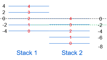
All z planes of Stack 2 are shifted by 3µm and now the z-plane 1 of Stack 1 and z-plane 3 of Stack 2 would be visible in the Correlative Workspace.
Aligning the whole session in z direction
Now the whole session with both images is shifted with a Relative Z Offset of 4µm.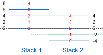
Now the first stack is out of range of the Global-Z slider, so the Correlative Workspace would show you plane 1 of Stack 2 and an empty frame where Stack 1 is located.