S&F Tab
Here you find helpful options and tools to draw in and relocate regions of interests (ROIs) or points of interest (POIs) within the sample image.
Options
|
Parameter |
Description |
|---|---|
|
Mirror Image |
Here you can mirror the image horizontally or vertically by using the two buttons at the right. The alignment of the images depends on the microscope (upright/inverted) and orientation of the sample holder. |
|
Keep tool |
Activated: Keeps the current tool active. That is helpful if you want to draw in more than one ROI/POI. |
|
Auto color |
Activated: Uses a new color for each new element which is drawn in. |
|
Snap to Pixel |
Activated: Draws in graphical elements using the pixel grid. |
|
Use fine calibration value |
Activated: Uses the measured fine calibration. The precision of relocation and therefore the quality of the overlay image can be improved by determination of an offset value. This value describes the offset between the loaded image and the live image. The defined offset value is only valid for the loaded image which you can see in the container. If another image is loaded or if you close the dialogue, the offset value will be deleted. More information, see Fine Calibration of the Sample Holder. |
|
Double click in image to move stage |
Activated: Moves the stage to the position you have double clicked on. |
|
Refocus after stage movement |
Activated: Adjusts the focus automatically after the stage has moved. |
|
Move stage in z-direction before x/y movement |
Activated: Moves the stage to the load position before it moves to the next correlative calibration marker. |
|
Show splitter view |
Activated: Activates Splitter Mode in the Center Screen Area. |
Regions, Find and Dimensions
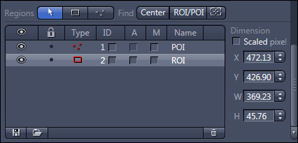
Regions and Find tool bar
|
Parameter |
Description |
|---|---|
|
|
Selects the ROIs or POIs in the image area. If you are currently in another mode, you can switch back to the Selection mode using this button. |
|
|
Draws in a rectangle (Region of Interest (ROI)) that is always parallel to the edges of the image. |
|
|
Draws in a marker point (Point of Interest (POI)). |
|
|
Moves the stage to the center of the opened image. |
|
|
Moves the stage to the selected ROI/POI. |
|
|
Shows the current stage position as a rectangle in the image. |


Dimension section
Here you see coordinates and dimensions of the selected graphical element in the list. If the Scaled checkbox is activated, the unit is µm, otherwise Pixel.
- Parameter X: Shows the horizontal position (x coordinate) of the center of the graphical element.
- Parameter Y: Shows the vertical position (v coordinate) of the center of the graphical element.
- Parameter W: Shows the width of the graphical element.
- Parameter H: Shows the height of the graphical element.
Graphical elements list
Here you see the list of all ROI/POI which are drawn in.
|
Parameter |
Description |
|---|---|
|
Eye symbol |
Shows or hides the ROI/POI in the image. |
|
Lock symbol |
Locks a ROI/POI to prevent changes. |
|
Type |
Displays the icon for the tool type (ROI/POI). To format a graphic element, double-click on the icon. The Format Graphic Elements dialog opens. |
|
ID |
Only visible if the Show All mode is activated. Displays the ID for the graphic element. To do this, activate the checkbox at the corresponding list entry. |
|
A |
Only visible if the Show All mode is activated. Displays annotations for a graphic element (ROI). To do this, activate the checkbox at the corresponding list entry. Then double click on the checkbox. The Format Graphic Elements dialog opens. Choose an annotation you want to have displayed within the image from the Annotation dropdown list. |
|
M |
Only visible if the Show All mode is activated. Displays measurement data for a graphic element. To do this, activate the checkbox at the corresponding list entry. |
|
Name |
Displays the name of the graphic element. To change the name, double-click in the Name field. Then enter the text of your choice. |