Measurement Features
Coordinate System
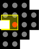
Some feature descriptions contain images with a coordinate system for illustrative purposes. Note that the actual coordinate system in the software is different and has its point of origin (0/0) in the top left corner of the image.
The software can automatically detect and measure various properties of objects.
Some general terms relevant for several feature descriptions are the following:
- Filled: A measurement feature with Filled in its name takes the entire region for the respective calculation, i.e. any holes the region might contain are included in the calculation.
- Unscaled: For features that are titled as Unscaled, the scaling of the image is not taken into account for the measurement. The values returned by these features have the unit pixel.
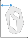
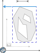
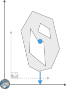
ACP X Unscaled
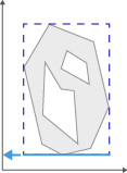
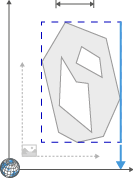
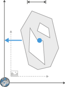
The x coordinate of the last pixel in the last line of a region.
To identify measurement objects, the image is scanned from bottom left to top right. The so-called ACP (anti-coincidence point) is the last point that has been identified for a new object. The parameter ACP X indicates the x-coordinate of this point.
- Unit: pixels
- Value range: 1 ... image size in x-direction
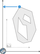
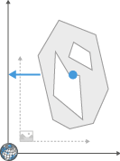
ACP X Unscaled WCS
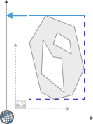
The x coordinate of the last pixel in the last line of a region.
To identify measurement objects, the image is scanned from bottom left to top right. The so-called ACP (anti-coincidence point) is the last point that has been identified for a new object. The parameter ACP X indicates the x-coordinate of this point in the world coordinate system (WCS).
- Unit: pixels
- Value range: 1 ... image size in x-direction
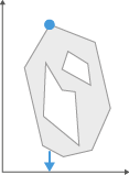
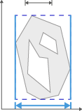
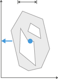
ACP Y Unscaled
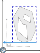
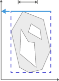
The y coordinate of the last pixel in the last line of a region.
To identify measurement objects, the image is scanned from bottom left to top right. The so-called ACP (anti-coincidence point) is the last point that has been identified for a new object. The parameter ACP Y indicates the y-coordinate of this point.
- Unit: pixels
- Value range: 1 ... image size in y-direction
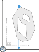
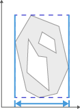
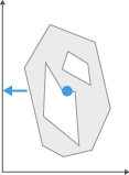
ACP Y Unscaled WCS
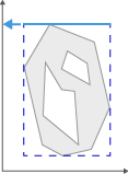
The y coordinate of the last pixel in the last line of a region.
To identify measurement objects, the image is scanned from bottom left to top right. The so-called ACP (anti-coincidence point) is the last point that has been identified for a new object. The parameter ACP Y indicates the y-coordinate of this point in the world coordinate system (WCS).
- Unit: pixels
- Value range: 1 ... world coordinate size in y-direction
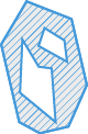
Area
Area of a region.
Area of a region excluding any holes it may contain. The areas of the holes are not included in the measurement. If you want to include them, use the Area filled parameter.
- Unit: Unit of area of the scaling assigned to the image (e.g. μm²)
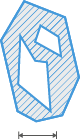
Area Convex (arivis)
Area of convex hull of a region.
The current region is surrounded by a convex polyline. The (filled!) area of the resulting region is then measured.
- Unit: Unit of area of the scaling assigned to the image (e.g. μm²)
Area Cut
Area of a region including the parts cut by a frame. Note that if you define Cut at Frame in the Frame step of the image analysis, the value of this parameter is identical to the value delivered by the Area feature.
- Unit: Unit of area of the scaling assigned to the image (e.g. μm²)
Area Cut Unscaled
Unscaled area of a region including the parts cut by a frame. Note that if you define Cut at Frame in the Frame step of the image analysis, the value of this parameter is identical to the value delivered by the Area Unscaled feature.
- Unit: pixels
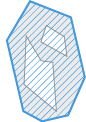
Area Filled

Area of filled region.
Area of a region including any holes it contains. The holes are interpreted as belonging to the region or are filled prior to the measurement. If you do not want the holes to be measured, use the Area parameter.
- Unit: Unit of area of the scaling assigned to the image (e.g. μm²)
Area Filled Unscaled
Area of filled region.
Area of a region including any holes it contains. The holes are interpreted as belonging to the region or are filled prior to the measurement. If you do not want the holes to be measured, use the Area parameter.
- Unit: pixels²
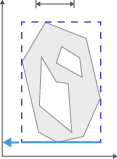
Area Frame
Returns the area of the measurement frame used in the image. If a ROI is defined in the Frame step of the wizard, this area is displayed, otherwise the area of the entire image is indicated. This also includes image areas without pixel values.
- Unit: µm2
Area Frame Unscaled
Returns the area of the measurement frame used in the image. If a ROI is defined in the Frame step of the wizard, this area is displayed, otherwise the area of the entire image is indicated. This also includes image areas without pixel values.
- Unit: pixels
Area Percentage of Holes
Area of the holes as a percentage of the overall area, i.e. the area of holes divided by the area of the segmented region.
Area Unscaled
Area of a region unscaled.
The Area unscaled parameter corresponds to the Area parameter. However, the scaling of the image is not taken into account for the measurement. The (unfilled!) area of a region is displayed in pixels in each case.
- Unit: pixels²
Bound Back
Indicates the back coordinate (highest value in z-direction) of the bounding box of a region. The box is drawn in parallel to the x, y and z axis.
- Unit: Unit of the scaling assigned to the image (e.g. μm)
Bound Back Unscaled
Indicates the back coordinate (highest value in z-direction) of the unscaled bounding box of a region. The box is drawn in parallel to the x, y and z axis.
- Unit: pixels
Bound Back Unscaled WCS
Indicates the back coordinate (highest value in z-direction) of the unscaled bounding box of a region in the world coordinate system (WCS). The box is drawn in parallel to the x, y and z axis.
- Unit: pixels
Bound Back WCS
Indicates the back coordinate (highest value in z-direction) of the bounding box of a region in the world coordinate system (WCS). The box is drawn in parallel to the x, y and z axis.
- Unit: Unit of the scaling assigned to the image (e.g. μm)
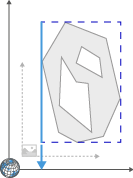
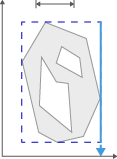
Bound Bottom
Minimum y-coordinate of the bounding box of a region.
Indicates the y-coordinate of the bottom edge of a bounding box for a region. The box is drawn in parallel to the x and y axis.
- Unit: Unit of the scaling assigned to the image (e.g. μm)
Bound Bottom Unscaled
Minimum y-coordinate of the bounding box of a region.
Indicates the y-coordinate of the bottom edge of a bounding box for a region. The box is drawn in parallel to the x and y axis.
- Unit: pixels
Bound Bottom Unscaled WCS
Minimum y-coordinate of the bounding box of a region.
Indicates the y-coordinate in the world coordinate system (WCS) of the bottom edge of a bounding box for a region. The box is drawn in parallel to the x and y axis.
- Unit: pixels
Bound Bottom WCS
Minimum y-coordinate of the bounding box of a region.
Indicates the y-coordinate in the world coordinate system (WCS) of the bottom edge of a bounding box for a region. The box is drawn in parallel to the x and y axis.
- Unit: Unit of the scaling assigned to the image (e.g. μm)
Bound Center
Bound Center X/Y/Z.
Indicates the x, y or z coordinate of the center of the bounding box for a region.
- Unit: Unit of the scaling assigned to the image (e.g. μm)
Bound Center Unscaled
Bound Center X/Y/Z Unscaled.
Indicates the x, y or z coordinate of the unscaled center of the bounding box for a region.
- Unit: pixels
Bound Center Unscaled WCS
Bound Center X/Y/Z Unscaled WCS.
Indicates the x, y or z coordinate of the unscaled center of the bounding box for a region in the world coordinate system (WCS).
- Unit: pixels
Bound Center WCS
Bound Center X/Y/Z WCS.
Indicates the x, y or z coordinate of the center of the bounding box for a region in the world coordinate system (WCS).
- Unit: Unit of the scaling assigned to the image (e.g. μm)
Bound Depth
Indicates the depth of the bounding box of a region, i.e. the "length" of the bounding box in z.
- Unit: Unit of the scaling assigned to the image (e.g. μm)
Bound Depth Unscaled
Indicates the depth of the unscaled bounding box of a region, i.e. the "length" of the bounding box in z.
- Unit: pixels
Bound Front
Indicates the front coordinate (smallest value in z-direction) of the bounding box of a region. The box is drawn in parallel to the x, y and z axis.
- Unit: Unit of the scaling assigned to the image (e.g. μm)
Bound Front Unscaled
Indicates the front coordinate (smallest value in z-direction) of the unscaled bounding box of a region. The box is drawn in parallel to the x, y and z axis.
- Unit: pixels
Bound Front Unscaled WCS
Indicates the front coordinate (smallest value in z-direction) of the unscaled bounding box of a region in the world coordinate system (WCS). The box is drawn in parallel to the x, y and z axis.
- Unit: pixels
Bound Front WCS
Indicates the front coordinate (smallest value in z-direction) of the bounding box of a region in the world coordinate system (WCS). The box is drawn in parallel to the x, y and z axis.
- Unit: Unit of the scaling assigned to the image (e.g. μm)
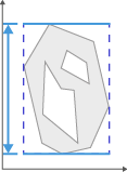
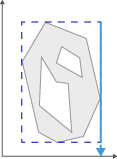
Bound Height
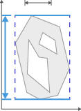
Indicates the height (size in y-direction) of a bounding box for a region. The box is drawn in parallel to the x and y axis.
- Unit: Unit of the scaling assigned to the image (e.g. μm)
- Formula: Bound top - Bound bottom
Bound Height Unscaled
Indicates the height (size in y-direction) of a bounding box for a region. The box is drawn in parallel to the x and y axis.
- Unit: pixels
- Formula: Bound top - Bound bottom
Bound Left
Minimum x-coordinate of the bounding box of a region.
Indicates the x coordinate of the left-hand edge of a bounding box for a region. The box is drawn in parallel to the x and y axis.
- Unit: Unit of the scaling assigned to the image (e.g. μm)
Bound Left Unscaled
Minimum x-coordinate of the bounding box of a region.
Indicates the x coordinate of the left-hand edge of a bounding box for a region. The box is drawn in parallel to the x and y axis.
- Unit: pixels
Bound Left Unscaled WCS
Minimum x-coordinate of the bounding box of a region.
Indicates the x coordinate in the world coordinate system (WCS) of the left-hand edge of a bounding box for a region. The box is drawn in parallel to the x and y axis.
- Unit: pixels
Bound Left WCS
Minimum x-coordinate of the bounding box of a region.
Indicates the x coordinate in the world coordinate system (WCS) of the left-hand edge of a bounding box for a region. The box is drawn in parallel to the x and y axis.
- Unit: Unit of the scaling assigned to the image (e.g. μm)
Bound Right
Maximum x-coordinate of the bounding box of a region.
Indicates the x coordinate of the right-hand edge of a bounding box for a region. The box is drawn in parallel to the x and y axis.
- Unit: Unit of the scaling assigned to the image (e.g. μm)
Bound Right Unscaled
Maximum x-coordinate of the bounding box of a region.
Indicates the x coordinate of the right-hand edge of a bounding box for a region. The box is drawn in parallel to the x and y axis.
- Unit: pixels
Bound Right Unscaled WCS
Maximum x-coordinate of the bounding box of a region.
Indicates the x coordinate in the world coordinate system (WCS) of the right-hand edge of a bounding box for a region. The box is drawn in parallel to the x and y axis.
- Unit: pixels
Bound Right WCS
Maximum x-coordinate of the bounding box of a region.
Indicates the x coordinate in the world coordinate system (WCS) of the right-hand edge of a bounding box for a region. The box is drawn in parallel to the x and y axis.
- Unit: Unit of the scaling assigned to the image (e.g. μm)
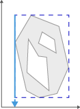
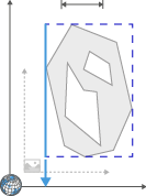
Bound Top
Maximum y-coordinate of the bounding box of a region.
Indicates the y-coordinate of the top edge of a bounding box for a region. The box is drawn in parallel to the x and y axis.
- Unit: Unit of the scaling assigned to the image (e.g. μm)
Bound Top Unscaled
Maximum y-coordinate of the bounding box of a region.
Indicates the y-coordinate of the top edge of a bounding box for a region. The box is drawn in parallel to the x and y axis.
- Unit: pixels
Bound Top Unscaled WCS
Maximum y-coordinate of the bounding box of a region.
Indicates the y coordinate in the world coordinate system (WCS) of the top edge of a bounding box for a region. The box is drawn in parallel to the x and y axis.
- Unit: pixels
Bound Top WCS
Maximum y-coordinate of the bounding box of a region.
Indicates the y coordinate in the world coordinate system (WCS) of the top edge of a bounding box for a region. The box is drawn in parallel to the x and y axis.
- Unit: Unit of the scaling assigned to the image (e.g. μm)
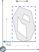
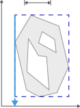
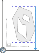
Bound Width
Indicates the width (size in x-direction) of a bounding box for a region. The box is drawn in parallel to the x and y axis.
- Formula: Bound right - Bound left
- Unit: Unit of the scaling assigned to the image (e.g. μm)
Bound Width Unscaled
Indicates the width (size in x-direction) of a bounding box for a region. The box is drawn in parallel to the x and y axis.
- Formula: Bound right - Bound left
- Unit: pixels
Center X
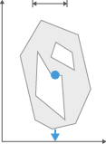
The x coordinate of the geometric center of gravity of a region.
Depending on the shape of the object, this point may also lie outside a region. The associated y-coordinate is determined via the Center Y parameter.
- Unit: Unit of the scaling assigned to the image (e.g. μm)
Center X Unscaled

The x coordinate of the geometric center of gravity of a region.
Depending on the shape of the object, this point may also lie outside a region. The associated y-coordinate is determined via the Center Y parameter.
- Unit: pixels
Center X Unscaled WCS

The x coordinate in the world coordinate system (WCS) of the geometric center of gravity of a region.
Depending on the shape of the object, this point may also lie outside a region. The associated y-coordinate is determined via the Center Y parameter.
- Unit: pixels
Center X WCS
The x coordinate in the world coordinate system (WCS) of the geometric center of gravity of a region.
Depending on the shape of the object, this point may also lie outside a region. The associated y-coordinate is determined via the Center Y parameter.
- Unit: Unit of the scaling assigned to the image (e.g. μm)
Center Y
The y coordinate of the geometric center of gravity of a region.
Depending on the shape of the object, this point may also lie outside a region. The associated x coordinate is determined via the Center X parameter.
- Unit: Unit of the scaling assigned to the image (e.g. μm)
Center Y Unscaled
The y coordinate of the geometric center of gravity of a region.
Depending on the shape of the object, this point may also lie outside a region. The associated x coordinate is determined via the Center X parameter.
- Unit: pixels
Center Y Unscaled WCS
The y coordinate in the world coordinate system (WCS) of the geometric center of gravity of a region.
Depending on the shape of the object, this point may also lie outside a region. The associated x coordinate is determined via the Center X parameter.
- Unit: pixels
Center Y WCS
The y coordinate in the world coordinate system (WCS) of the geometric center of gravity of a region.
Depending on the shape of the object, this point may also lie outside a region. The associated x coordinate is determined via the Center X parameter.
- Unit: Unit of the scaling assigned to the image (e.g. μm)
Center Z
Indicates the z coordinate of the geometric center of gravity of a region.
Depending on the shape of the object, this point can also lie outside a region. The associated x and y coordinates are determined by the Center X and Center Y features.
- Unit: Unit of the scaling assigned to the image (e.g. μm)
Center Z Unscaled
Indicates the z coordinate of the unscaled geometric center of gravity of a region.
Depending on the shape of the object, this point can also lie outside a region. The associated x and y coordinates are determined by the Center X Unscaled and Center Y Unscaled features.
- Unit: pixels
Center Z Unscaled WCS
Indicates the z coordinate of the unscaled geometric center of gravity of a region in the world coordinate system (WCS).
Depending on the shape of the object, this point can also lie outside a region. The associated x and y coordinates are determined by the Center X Unscaled WCS and Center Y Unscaled WCS features.
- Unit: pixels
Center Z WCS
Indicates the z coordinate of the geometric center of gravity of a region in the world coordinate system (WCS).
Depending on the shape of the object, this point can also lie outside a region. The associated x and y coordinates are determined by the Center X WCS and Center Y WCS features.
- Unit: Unit of the scaling assigned to the image (e.g. μm)
Circularity (arivis)
Sqrt(Roundness) = Sqrt(4 × Area / (π × Feret Maximum (arivis)²))
Compactness (arivis)
4 × π × Area / Perimeter Convex (arivis)²
Convexity (arivis)
(Perimeter Convex (arivis) / Perimeter Crofton)2
Count
Returns the count of analyzed objects.
Count Objects Direct Subclasses
Returns the count of analyzed objects in the direct subclasses.
Note that this feature only considers values of direct subclasses of a class, i.e. subclasses that are directly on the next lower hierarchy level in the class list. Values of subclasses on lower hierarchy levels ("subclass of a subclass") are not considered.
Count per mm2
Returns the count of analyzed objects per mm2.
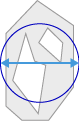
Diameter
Diameter of a circle/sphere with an area/volume equal to that of the object.
The object is measured using the Area feature. A circle with the same area as the object is created. The diameter of this circle is returned.
In case of a three dimensional analysis, the equivalent sphere with the Volume of the region is measured and the diameter of the sphere is returned.
- Formula 2D: Sqrt ((4/π)*Area)
- Formula 3D: Pow(6*Volume/π, 1/3)
- Unit: Unit of the scaling assigned to the image (e.g. μm)
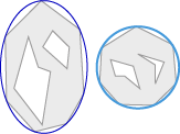
Diameter Maximum Inscribed Circle
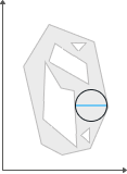
Diameter of the largest circle that can be inscribed inside an area.
The object is transformed into a binary image. A distance transform is applied on the binary image which calculates the largest distance to the outline of the object or any holes the object contains. Extracting the point with the largest distance yields the maximum inscribed circle. The diameter is twice the largest distance.
- Unit: Unit of the scaling assigned to the image (e.g. μm)
Diameter Maximum Inscribed Circle Unscaled
Diameter of the largest circle that can be inscribed inside an area.
The object is transformed into a binary image. A distance transform is applied on the binary image which calculates the largest distance to the outline of the object or any holes the object contains. Extracting the point with the largest distance yields the maximum inscribed circle. The diameter is twice the largest distance.
- Unit: pixel
Diameter Unscaled
Unscaled diameter of a circle/sphere with an area/volume equal to that of the object.
The object is measured using the Area Unscaled feature. A circle with the same area as the object is created. The diameter of this circle is returned.
In case of a three dimensional analysis, the equivalent sphere with the Volume Unscaled of the region is measured and the diameter of the sphere is returned.
- Formula 2D: Sqrt ((4/π)*Area Unscaled)
- Formula 3D: Pow(6*Volume Unscaled/π, 1/3)
- Unit: pixels
Ellipse Angle
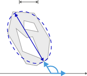
Angle of the major axis of the ellipse.
The major axis of an ellipse with the same geometric moment of inertia as the current region is determined in accordance with the Ellipse major parameter. The angle to the x-axis is then determined. The indication of the angle always relates to a counterclockwise direction.
- Unit: degrees
- Value range: 0 ... 180°
Ellipse Angle Unscaled
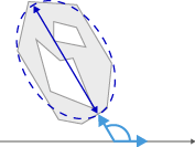
Angle of the major axis of the ellipse.
The major axis of an ellipse with the same geometric moment of inertia as the current region is determined in accordance with the Ellipse major parameter. The angle to the x-axis is then determined. The indication of the angle always relates to a counterclockwise direction.
- Unit: degrees
- Value range: 0 ... 180°
This tool uses unscaled pixels for calculating the angle. The results may differ from the results of Ellipse Angle.
Ellipse Semi-Major
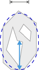
Length of the semi-major axis of the ellipse.
Length of the semi-major axis of an ellipse with the same geometric moment of inertia as the region. The moment of inertia is calculated about the center of gravity of the region.
- Unit: Unit of the scaling assigned to the image (e.g. μm)
Ellipse Semi-Major Unscaled
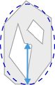
Length of the semi-major axis of the ellipse.
Length of the semi-major axis of an ellipse with the same geometric moment of inertia as the region. The moment of inertia is calculated about the center of gravity of the region.
- Unit: pixels
Ellipse Semi-Minor
Length of the semi-minor axis of the ellipse.
Length of the semi-minor axis of an ellipse with the same geometric moment of inertia as the region. The moment of inertia is calculated about the center of gravity of the region.
- Unit: Unit of the scaling assigned to the image (e.g. μm)
Ellipse Semi-Minor Unscaled
Length of the semi-minor axis of the ellipse.
Length of the semi-minor axis of an ellipse with the same geometric moment of inertia as the region. The moment of inertia is calculated about the center of gravity of the region.
- Unit: pixels
Ellipsoid Semi-Major
Calculates the length of the semi-major axis of the equivalent ellipsoid of the region.
- Unit: Unit of the scaling assigned to the image (e.g. μm)
Ellipsoid Semi-Major Unscaled
Calculates the length of the semi-major axis of the equivalent unscaled ellipsoid of the region.
- Unit: pixels
Ellipsoid Semi-Mean
Calculates the length of the semi-mean axis of the equivalent ellipsoid of the region, i.e. half the length of the medium/middle axis of the three dimensional ellipsoid.
- Unit: Unit of the scaling assigned to the image (e.g. μm)
Ellipsoid Semi-Mean Unscaled
Calculates the length of the semi-mean axis of the equivalent unscaled ellipsoid of the region, i.e. half the length of the medium/middle axis of the three dimensional ellipsoid.
- Unit: pixels
Ellipsoid Semi-Minor
Calculates the length of the semi-minor axis of the equivalent ellipsoid of the region.
- Unit: Unit of the scaling assigned to the image (e.g. μm)
Ellipsoid Semi-Minor Unscaled
Calculates the length of the semi-minor axis of the equivalent unscaled ellipsoid of the region.
- Unit: pixels
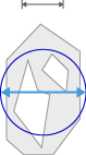
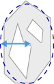
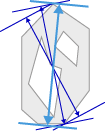
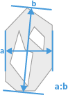
Feret Maximum
Maximum feret of a region.
The maximum feret of a region is determined on the basis of distance measurements. Two straight lines are positioned on opposite sides of the object, like a sliding caliper, at 128 angle positions. The corresponding distance is measured for each angle position. The maximum value determined is the maximum feret.
- Unit: Unit of the scaling assigned to the image (e.g. μm)
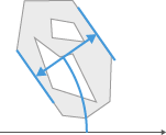
Feret Maximum Angle (arivis)
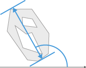
Angle of the maximum feret of a region in relation to the x-axis.
The maximum feret is determined as described in Feret Maximum (arivis). The angle of the maximum feret in relation to the x-axis is then determined. The indication of the angle always relates to a counterclockwise direction.
- Unit: degrees
- Value range: -90° ... 90°
Feret Maximum Unscaled (arivis)
Maximum feret of a region.
The maximum feret of a region is determined on the basis of distance measurements. The calculation uses the method of rotating calipers. Two parallel tangent lines are positioned on opposite sides of the object and rotated around the object to determine the largest distance. The corresponding distance is measured for each angle position. The maximum value determined is the maximum feret.
- Unit: pixels
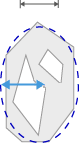
Feret Minimum
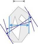
Minimum feret of a region.
The minimum feret of a region is determined on the basis of distance measurements. Two straight lines are positioned on opposite sides of the object, like a sliding caliper, at 128 angle positions. The corresponding distance is measured for each angle position. The minimum value determined is the minimum feret.
- Unit: Unit of the scaling assigned to the image (e.g. μm)
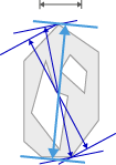
Feret Minimum Angle (arivis)
Angle of the minimum feret of a region in relation to the x-axis.
The minimum feret is determined as described in Feret Minimum (arivis). The angle of the minimum feret in relation to the x-axis is then determined. The indication of the angle always relates to a counterclockwise direction.
- Unit: degrees
- Value range: -90° ... 90°
Feret Minimum Unscaled (arivis)
Minimum feret of a region.
The minimum feret of a region is determined on the basis of distance measurements. The calculation uses the method of rotating calipers. Two parallel tangent lines are positioned on opposite sides of the object and rotated around the object to determine the smallest distance. The corresponding distance is measured for each angle position. The minimum value determined is the minimum feret.
- Unit: pixels
Feret Ratio (arivis)
Feret ratio.
The ratio of Feret Minimum (arivis) to Feret Maximum (arivis) is calculated. This ratio makes it possible to make statements on the form of the measured objects. If the feret ratio has a low value, long, elongated objects are present. Values approaching 1 indicate the presence of compact or circular objects, as in this case Feret Minimum (arivis) and Feret Maximum (arivis) have very similar values. The Form Circle is also suitable for making statements on the circularity of an object.
- Formula: Feret Minimum (arivis) / Feret Maximum (arivis)
- Unit: none
- Value range: 0 ... 1
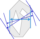
Feret Vertical to Maximum (arivis)
The feret perpendicular to the maximum feret of a region.
- Unit: Unit of the scaling assigned to the image (e.g. µm)
Fiber Length
Length of a fiber-like region.
To calculate the fiber length, a structure that is actually similar to a fiber is required. Here it is not the distance between a start and end point that is determined. The check can be done using the Form circle, among other things.
- Formula: ¼ × (Perimeter + (Sqrt (Perimeter² - 16 × Area))
- Unit: Unit of the scaling assigned to the image (e.g. μm)
Fiber Length Unscaled
Length of a fiber-like region.
To calculate the fiber length, a structure that is actually similar to a fiber is required. Here it is not the distance between a start and end point that is determined. The check can be done using the Form Circle, among other things.
- Formula: ¼ × (Perimeter Unscaled + (Sqrt (Perimeter Unscaled² - 16 × Area Unscaled))
- Unit: pixels
Form Circle
Form factor of a region.
Describes the form of a region on the basis of its circularity. A perfect circle is given the value 1. The more elongated the region is, the smaller the form factor. The calculation is based on the Area filled and Perimeter Crofton parameters.
- Formula: 4 × π × Area / PerimeterCrofton²
- Unit: none
- Value range: 0...1
Frame Area Percentage
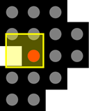
The percentage of the area of the regions in relation to the area of all frames in the respective scene. This also includes image areas without pixel values. If you have defined no frame, this feature returns the percentage in relation to the whole image, i.e. the same value as Image Plane Area Percentage. In case of images with multiple scenes, the features is always calculated based on the area of a single scene.
Note that if your image does not contain areas without pixel values and you have not drawn a frame into the image, the following features all have the same result: Frame Area Percentage, Frame Data Area Percentage, Image Plane Area Percentage, and Image Plane Data Area Percentage.
Frame Area Percentage Cut
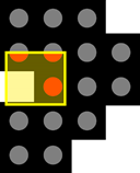
The percentage of the area of the regions including regions that are cut by the frame in relation to the area of all frames in the respective scene. This also includes image areas without pixel values. In case of images with multiple scenes, the features is always calculated based on the area of a single scene.
Frame Data Area
Returns the area of the measurement frame used in the image. If a ROI is defined in the Frame step of the wizard, this area is displayed, otherwise the area of the entire image is indicated. This only incorporates image areas which contain pixel values.
- Unit: Unit of area of the scaling assigned to the image (e.g. μm2)
Frame Data Area Percentage
The percentage of the area of the regions in relation to the area of all frames in the respective scene. This only incorporates image areas which contain pixel values. If you have defined no frame, this feature returns the percentage in relation to the whole image, i.e. the same value as Image Plane Data Area Percentage. In case of images with multiple scenes, the features is always calculated based on the area of a single scene.
Note that if your image does not contain areas without pixel values and you have not drawn a frame into the image, the following features all have the same result: Frame Area Percentage, Frame Data Area Percentage, Image Plane Area Percentage, and Image Plane Data Area Percentage.
Frame Data Area Unscaled
Returns the unscaled area of the measurement frame used in the image. If a ROI is defined in the Frame step of the wizard, this area is displayed, otherwise the area of the entire image is indicated. This only incorporates image areas which contain pixel values.
- Unit: pixels
ID
Sequential ID of the object.
ID Object Storage
Returns the ID of the segmented object that is saved in the object store.
ON THIS PAGE
- Measurement Features
- ACP X Unscaled
- ACP X Unscaled WCS
- ACP Y Unscaled
- ACP Y Unscaled WCS
- Area
- Area Convex (arivis)
- Area Cut
- Area Cut Unscaled
- Area Filled
- Area Filled Unscaled
- Area Frame
- Area Frame Unscaled
- Area Percentage of Holes
- Area Unscaled
- Bound Back
- Bound Back Unscaled
- Bound Back Unscaled WCS
- Bound Back WCS
- Bound Bottom
- Bound Bottom Unscaled
- Bound Bottom Unscaled WCS
- Bound Bottom WCS
- Bound Center
- Bound Center Unscaled
- Bound Center Unscaled WCS
- Bound Center WCS
- Bound Depth
- Bound Depth Unscaled
- Bound Front
- Bound Front Unscaled
- Bound Front Unscaled WCS
- Bound Front WCS
- Bound Height
- Bound Height Unscaled
- Bound Left
- Bound Left Unscaled
- Bound Left Unscaled WCS
- Bound Left WCS
- Bound Right
- Bound Right Unscaled
- Bound Right Unscaled WCS
- Bound Right WCS
- Bound Top
- Bound Top Unscaled
- Bound Top Unscaled WCS
- Bound Top WCS
- Bound Width
- Bound Width Unscaled
- Center X
- Center X Unscaled
- Center X Unscaled WCS
- Center X WCS
- Center Y
- Center Y Unscaled
- Center Y Unscaled WCS
- Center Y WCS
- Center Z
- Center Z Unscaled
- Center Z Unscaled WCS
- Center Z WCS
- Circularity (arivis)
- Compactness (arivis)
- Convexity (arivis)
- Count
- Count Objects Direct Subclasses
- Count per mm2
- Diameter
- Diameter Maximum Inscribed Circle
- Diameter Maximum Inscribed Circle Unscaled
- Diameter Unscaled
- Ellipse Angle
- Ellipse Angle Unscaled
- Ellipse Semi-Major
- Ellipse Semi-Major Unscaled
- Ellipse Semi-Minor
- Ellipse Semi-Minor Unscaled
- Ellipsoid Semi-Major
- Ellipsoid Semi-Major Unscaled
- Ellipsoid Semi-Mean
- Ellipsoid Semi-Mean Unscaled
- Ellipsoid Semi-Minor
- Ellipsoid Semi-Minor Unscaled
- Feret Maximum
- Feret Maximum Angle (arivis)
- Feret Maximum Unscaled (arivis)
- Feret Minimum
- Feret Minimum Angle (arivis)
- Feret Minimum Unscaled (arivis)
- Feret Ratio (arivis)
- Feret Vertical to Maximum (arivis)
- Fiber Length
- Fiber Length Unscaled
- Form Circle
- Frame Area Percentage
- Frame Area Percentage Cut
- Frame Data Area
- Frame Data Area Percentage
- Frame Data Area Unscaled
- ID
- ID Object Storage