3D View
This view is only available if:
- you have loaded or acquired a z-stack image.
- a suitable NVIDIA or AMD graphics card with full OpenGL 4.3 or higher functionality is present.
3D View employs 3D rendering technology which requires access to advanced OpenGL functionality. For full functionality this means that a modern dedicated graphic card (NVIDIA or AMD technology) has to be present.
|
1 |
Tool Bars |
|
2 |
3D View |
|
3 |
Analysis Object Table |
|
4 |
Summary Table |
|
5 |
View Options |
3D Tab
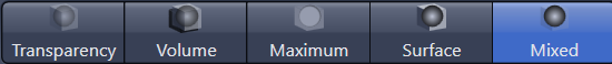
Here you can specify which projection/rendering mode you want to use to display the 3D volume. There are 5 view modes available. To activate the desired view mode, click on the corresponding button. An activated button (respectively the mode) appears in blue color.
|
Parameter |
Description |
|
|---|---|---|
|
Transparency |
Activates the Transparency rendering mode. |
|
|
Volume |
Activates the Volume mode. |
|
|
Maximum |
Activates the Maximum intensity projection mode. |
|
|
Surface |
Activates the Surface reconstruction mode |
|
|
Mixed |
Activates a combination of transparency rendering and surface reconstruction mode |
|
|
Precise/Fast |
Adjust the level of detail of the 3d volume here.
|
|
|
Update on completed frame |
Only available, if Follow Acquisition on the Dimensions tab is activated. Activated: During acquisition, the 3D View is only updated after the acquisition of a stack has been completed. |
|
|
Depth coding |
Only active if Transparency, Maximum or Mixed mode is activated. Activated: Replaces the channel colors of the volume with a rainbow color table where the color represents the depth of the stack. A palette is shown which matches the colors to a given depth (in scaled units). |
|
|
Toggle Clipping Planes |
By activating or deactivating the buttons you can show or hide the corresponding clipping planes in the 3D volume. If you right-click on an activated button, a shortcut menu opens. Here you can select whether you want the back (Clip Back), front (Clip Front) or both sides of the 3D volume to be clipped. You can also specify the Style of the clipping plane. Under each button is a slider. You can use this to move the relevant clipping plane within the volume. |
|
|
Wedge |
Activated: Activates two texture planes. Only the sector between the planes is cut out. You can select which planes you want to be used for the wedge function from the dropdown list. The selection is also visible in the relevant buttons. |
|
|
Stored |
Here you can select saved 3D settings. |
|
|
|
Opens the options menu. |
|
|
– |
New |
Creates a new settings file that is given a name automatically and has the file extension *.cz3dr. The settings file can be found in the user path under \My Documents\Carl Zeiss\ZEN\Documents\3Dxl render settings. |
|
– |
Delete |
Deletes the selected settings file from the hard drive. |
|
– |
Rename |
Renames the selected settings file. Enter a new name in the input field and confirm with OK. |
|
– |
Save As |
Saves the selected settings file under a different name. |
|
– |
Import |
Imports a *.cz3dr file and applies it to the current image. |
|
– |
Export |
Exports a *.cz3dr file to a different location. |
|
Create Image |
Creates a new image from the current view. This image is a 24 bit RGB color image. All graphic elements, such as annotations, are burnt in. In the dropdown left of the button you can select the resolution for the image that is created. |
|

Clipping Tab
Only visible if the Show All mode is activated.
Here you can edit clipping planes. To select a clipping plane, click on the corresponding button. The editing functions which you can use to modify the selected clipping plane become visible when you activate the specific clipping plane.
On the Clipping tab you can edit the clipping planes. On the 3D tab you can activate or deactivate the relevant clipping planes in the 3D volume.
|
Parameter |
Description |
|---|---|
|
Show All Clipping Planes |
Activated: Automatically inserts all 3 clipping planes into the 3D volume. Additionally the editing functions for each clipping plane were activated automatically. |
|
|
Activates the editing functions for the X/Y clipping plane. |
|
|
Activates the editing functions for the X/Z clipping plane. |
|
|
Activates the editing functions for the Y/Z clipping plane. |
|
Activate |
Activated: Activates the selected clipping plane in the 3D volume. The corresponding settings become visible. You will find a detailed description of the settings in the list below. Note: Each plane is positioned at the center of the 3D volume and aligned orthogonally (in the X/Y, X/Z, Y/Z direction). |
|
Reset All |
Resets all parameters to the original values. |


The following parameters are only visible if the Activate checkbox is activated and a clipping plane has been selected.
|
Parameter |
Description |
|
|---|---|---|
|
Clipping Plane Style |
Change the display of the selected clipping plane using the dropdown list to the right of the Activate checkbox. The following settings are available: |
|
|
- |
Invisible |
The plane is invisible. |
|
- |
Colored |
The plane is displayed in color. The frame color is used with 50% transparency here. |
|
- |
Binary |
The data above the threshold value that are touched by the clipping plane are displayed in binary form as a white area. Black pixels are non-transparent. |
|
- |
Transparent |
The data that are touched by the clipping plane are displayed as they are in Transparent view mode, but in 2 dimensions. The ramp for the transparency is linear here. Black pixels are transparent. |
|
- |
Textured opaque |
The display appears as it does with the Textured setting. Black pixels do not let any light through, however, meaning that the render data behind them are not displayed. |
|
Outline |
Activated: Displays the frame of the selected clipping plane. Enter the frame color via the color field. |
|
|
Clip Front |
Activated: Clips the front of the 3D volume. |
|
|
Clip Back |
Activated: Clips the back of the 3D volume. |
|
|
Clip Transparency |
Only active if Mixed view mode is activated. Activated: In addition to the surface data, also clips the transparency data. |
|
|
Clip Surface Channels |
Only visible if Surface or Mixed view mode is activated. Here you can enter which channel you want to be clipped using the channel buttons. |
|
|
Position |
Here you can enter the position of the selected clipping plane. |
|
|
<X |
Here you can enter the X angle for the selected clipping plane. |
|
|
<Y |
Here you can enter the Y angle for the selected clipping plane. |
|
|
Reset Orientation |
Resets the selected clipping plane to the original position. |
|
Series Tab
Here you can create render series of individual views, which you can later view and export as a movie. The tab contains different control elements depending on the Render Series type. The following parameters are the same for all render series types: Render Series section, Stored section, Apply button and Fixed Resolution checkbox.
|
Parameter |
Description |
|
|---|---|---|
|
Render Series |
Here you can select the desired series mode. Depending on the chosen render series type, different parameters are displayed. |
|
|
- |
Turn Around X |
Define the start/stop angle and the rotation direction around the X axis. |
|
- |
Turn Around Y |
Only visible in the 3D view. Define the start/stop angle and the rotation direction around the Y axis. |
|
- |
Turn Around Z |
Define the start/stop angle and the rotation direction around the Z axis. |
|
- |
Start/Stop |
Define the angle and zoom settings for the start and end position of your series. The intermediate positions are interpolated evenly. |
|
- |
Position List |
Define any number of positions. The positions can each have completely different rotation, zoom and illumination settings. |
|
- |
Over Time |
Only visible in the 2.5D view. |
|
Apply |
Calculates the series. A new image document is opened in the Center Screen Area. You can view the series by clicking on the Play button in the Dimensions tab. |
|
|
Stored |
Only visible if Show All is activated. |
|
|
|
Clicking on the button opens a shortcut menu with the following options: |
|
|
- |
New |
Creates a new settings file (*.czsht). This file can be found in the user's local document path (e.g. \My Documents\Carl Zeiss\ZEN\Documents, in a corresponding subfolder). |
|
- |
Delete |
Deletes the selected settings file. |
|
- |
Rename |
Opens a dialog to rename the selected settings file. |
|
- |
Save As |
Saves a copy of the currently selected settings file under a different name. |
|
- |
Save |
Saves changes to a currently selected settings file. |
|
- |
Import |
Imports a setting files from the hard disk. |
|
- |
Export |
Exports a setting files to the hard disk. |
|
Preview |
Shows a preview of the series to be created. Use the |
|
|
Frames |
Sets the number of individual frames that the series consist of after the calculation. The more individual images that you specify here, the more fluidly the scene transitions will be displayed later. Select predefined values from the dropdown list (e.g. 20 or 100 frames). |
|
|
Fixed Resolution |
Only visible if Show All is activated. As a rule, the image series is calculated using the current screen resolution. If you want to set a different format for the series, activate the checkbox. In the input fields that are now visible you can enter the width and height in pixels with which you want the series to be created. |
|


The following parameters are only available if you have selected Turn Around X/Y/Z under Render Series:
- The X rotation, Y rotation and Z render series types all have the same control elements and differ only in the axis around which the rotation is calculated.
- The preview function is not available for these types of series.
|
Parameter |
Description |
|
|---|---|---|
|
360° Panorama |
Select 360° panorama, if you want to generate a complete rotation series. |
|
|
Partial Panorama |
If you select partial panorama, you can specify the starting angle and stopping angle that you want to use for the series. To do this, enter the desired values in the input fields or adjust it in the graphical representation of the rotation circle at the right of the input fields. |
|
|
- |
Start Angle |
Determines the starting angle. |
|
- |
Stop Angle |
Determines the stop angle. |
|
- |
Direction |
Determines the direction of rotation. |
|
- |
|
When you are configuring a partial panorama, the desired angles can also be determined easily using the circular control element: Grab the white start/stop points with the mouse and position these accordingly on the circle. The number of individual images is also displayed here. |

The following parameters are only available if you have selected Start/Stop under Render Series:
|
Parameter |
Description |
|---|---|
|
Start Position |
You can position the volume in the image area as required using the mouse. The geometric parameters are displayed in the input fields. You can also determine the Camera Position and the Look At parameters for X, Y or Z and the angle directly using the input fields or the slider. All changes are displayed immediately in the image area. |
|
Stop Position |
You can position the volume in the image area as required using the mouse. The geometric parameters are displayed in the input fields. You can also determine the Camera Position and the Look At parameters for X, Y or Z and the angle directly using the input fields or the slider. All changes are displayed immediately in the image area. |
The following parameters are only available if you have selected Position list under Render Series:
|
Parameter |
Description |
|
|---|---|---|
|
Add |
Adds the current position to the position list. |
|
|
Insert |
Inserts a new position between two existing positions. |
|
|
Position list |
Each position is displayed in the list with its X, Y, Z angle and zoom level. If you want to delete all positions, click Clear List. |
|
|
Additional Parameters |
You can determine which of the following parameters you want to be taken into consideration when the series is calculated. |
|
|
- |
Light |
Includes illumination parameters. |
|
- |
Transparency |
Includes transparency settings (not active in Surface mode). |
|
- |
Background |
Includes color and distance of the background. |
|
- |
Time |
Includes time series parameters (only active for time series images). |
|
- |
Camera |
Includes camera settings, e.g. viewing angle (from the 3D/virtual camera). |
|
- |
Planes |
Includes planes settings (not active in Shadow mode). |
|
- |
Surface |
Includes surface settings (only active in Surface and Mixed mode). |

Measurements Tab
Only visible if the Show All mode is activated.
Here you can perform interactive measurements in the 3D volume. Note that measurements are not possible in Shadow projection mode. The measurements can be drawn in directly in the 3D volume using different tools. The measurement results are displayed in a list at the right of the image area.
|
Parameter |
Description |
|
|---|---|---|
|
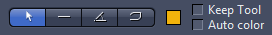
Tool bar |
|
|
|
- |
|
Changes the mouse pointer to Selection mode. Use this to select measurements in the 3D volume in order to change them. |
|
- |
|
Use this to measure the length of a line in µm. Click once on the starting point and hold down the mouse button. Then drag the mouse to the end point and release the mouse button again. The measurement is complete. The result of the measurement is displayed in the list to the right of the image area. |
|
- |
|
Use this to measure the angle between two connected legs. First define the starting point. Then use the mouse to drag the first leg to the desired first end point. Define the second leg by clicking on the second end point. The angle measurement ends with a display of the angle measured (in degrees). The result of the measurement is displayed in the list to the right of the image area. |
|
- |
|
Use this to measure along a line with any number of segments. Click from corner point to corner point. Complete the measurement by right-clicking. The result of the measurement is displayed in the list to the right of the image area. |
|
- |
Color selection |
Here you can select a color for the tool you want to draw in. Simply click on the colored rectangle and choose a color from the list. |
|
- |
Keep Tool |
Activated: Keeps the selected tool active. |
|
- |
Auto Color |
Activated: Automatically changes the color of the drawn-in tool. |


|
Parameter |
Description |
|
|---|---|---|
|
Show Measurements |
Activated: Shows the measurements in the 3D volume or in the list of measured values at the right of the image area. |
|
|
- |
On top |
Activated: All drawn-in measurement tools appear in the foreground, even if these are in fact obscured by image structures. |
|
Display Values |
||
|
- |
on the objects |
Activated: Displays the measured values in the 3D volume. |
|
- |
as list |
Activated: Displays the measured values in the measurement data table. |
|
Delete Selected |
Only active if a measurement tool has been selected in the 3D volume. |
|
|
Delete All |
Deletes all measurement tools from the 3D volume. |
|
3D Graphics Tab
Only visible if the Show All mode is activated.
|
Parameter |
Description |
|
|---|---|---|
|
Tool bar |
|
|
|
- |
|
Changes the mouse pointer to Selection mode. Use this to select measurements in the 3D volume in order to change them. |
|
- |
|
Use this to measure the length of a line in µm. Click once on the starting point and hold down the mouse button. Then drag the mouse to the end point and release the mouse button again. The measurement is complete. The result of the measurement is displayed in the list to the right of the image area. |
|
- |
|
Use this to measure the angle between two connected legs. First define the starting point. Then use the mouse to drag the first leg to the desired first end point. Define the second leg by clicking on the second end point. The angle measurement ends with a display of the angle measured (in degrees). The result of the measurement is displayed in the list to the right of the image area. |
|
- |
|
Use this to measure along a line with any number of segments. Click from corner point to corner point. Complete the measurement by right-clicking. The result of the measurement is displayed in the list to the right of the image area. |
|
- |
Color selection |
Here you can select a color for the tool you want to draw in. Simply click on the colored rectangle and choose a color from the list. |
|
- |
Keep Tool |
Activated: Keeps the selected tool active. |
|
- |
Auto Color |
Activated: Automatically changes the color of the drawn-in tool. |
|
Parameter |
Description |
|
|---|---|---|
|
3D Measurements |
All measurement contained in the 3D volume are displayed here. The list contains the following columns: |
|
|
- |
Eye icon |
Here you can select whether or not a measurement tool is displayed in the image. If you click in the title field of the column, the setting is made simultaneously for all entries. |
|
- |
Lock icon |
Not activated for the 3D view. |
|
- |
Type |
Displays the type of a tool. If you click on the icon, you can change the color of the tool. |
|
- |
ID |
Displays the unique identification number of the measurement tool. |
|
- |
A |
No function. |
|
- |
M |
Activated: Displays the measurement data in the image. This setting is applied to all entries simultaneously, i.e. the data of all entries is displayed. |
|
- |
Name |
Displays the name of the tool. To change the name, double-click on the entry, enter a new name and confirm by pressing Enter. |