Acquiring the LM image
The image acquisition will be performed by the help of the Acquisition Wizard which is opened if you click on Start Acquisition Wizard in the Correlative Array Tomography tool.
The wizard contains the following 7 steps:
Acquiring the Overview Image
Take care that the Auto checkbox on the Dimensions tab is deactivated.
- You have started the Acquisition Wizard via the CAT tool.
- You are in step 1/7 Overview Imaging.
- Check if Image Acquisition mode is selected. This is the default setting when entering the wizard.
- From the Experiment dropdown list select the experiment that you have prepared in advance.
- From the Objective list select an objective with a low magnification, e.g. 5x.
- Select the Channel and the Light Source you want to use for acquiring the overview image. For the overview image we recommend selecting Phase contrast as channel mode.
- Move the stage to the upper left corner of your sample.
- Click on Set start position to define the starting position of the overview image.
- Move the stage to the bottom right corner of your sample.
- Click on Set end position to define the end position of the overview image.
- Click on Acquire Overview Image.
- The overview image will be acquired. Then you should see the complete sample showing all ribbons you want to image.
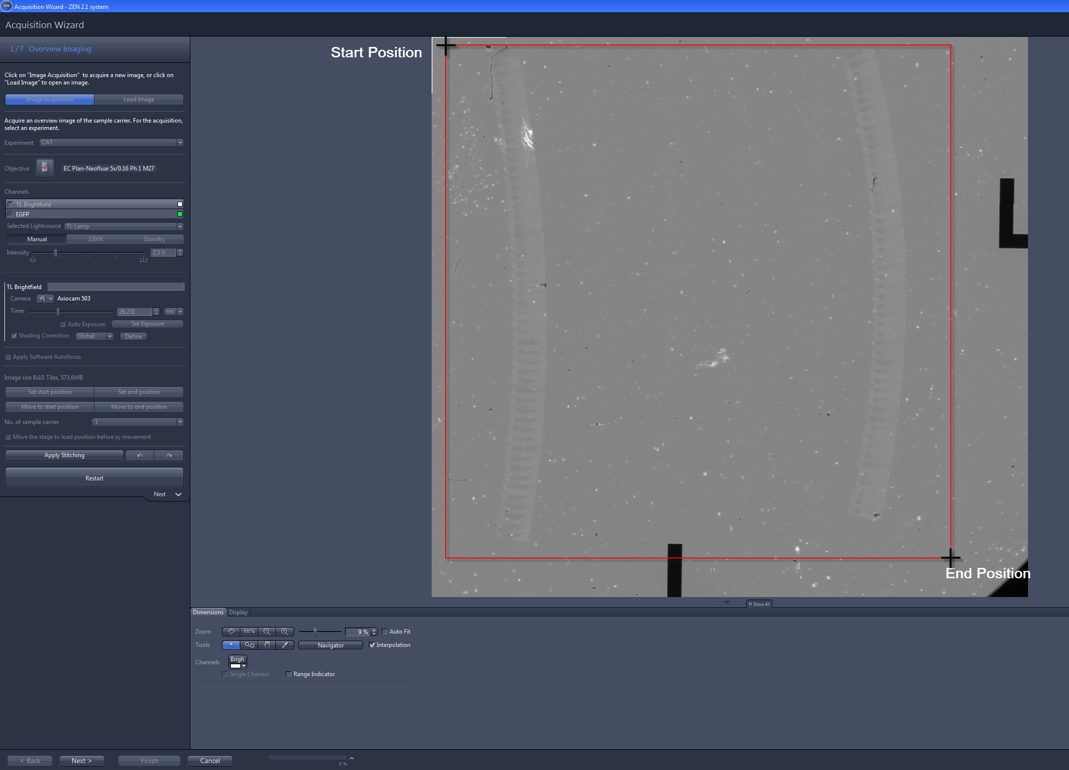
- Click on Apply Stitching to remove the offset between the single tile images.
- You have successfully acquired the overview image. You can now continue with the next step by clicking on Next.
Defining the Ribbons
When no detailed sample information is necessary to identify regions of interest within the sections, you can skip this step and the following step 3 Ribbon imaging as well. You can then go on with the wizard step 4 Section specification.
- You are in step 2/7 Ribbon Definition of the Acquisition Wizard.
- Use the tools on the Ribbon Definition tab to mark the contour lines of the ribbons which should be imaged. The contour lines are displayed in yellow color.
- The software will automatically create as many tiles as necessary for imaging the ribbons. The number of the tiles depend on the selected objective. The frames of the tiles will be displayed in red color.
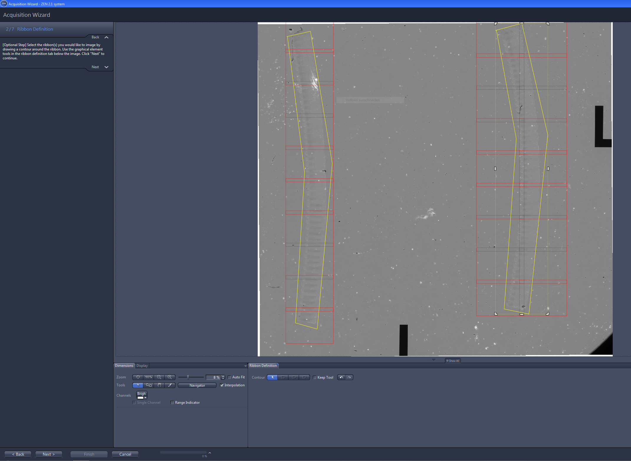
- When you have marked the contours, click on Next.
Imaging the Ribbons
Please note that this is an optional step and must be performed only when you have defined ribbons as described in step 2. In summary, you have to perform the same actions mentioned in step 1 but you should use an objective with higher magnification and apply the Global focus strategy under Focus Surface.
- You are in step 3/7 Ribbon Imaging.
- Under Objective select an objective with a higher magnification than for the overview image, e.g. 10x. The objective should enable you to clearly recognize the structures of interest on your sample.
- Under Focus Surface select Global (all Regions/ Ribbons).
- Click on Distribute Support Points....
- The support points will be distributed automatically over the ribbons. They are displayed as yellow circles with a point in the middle.
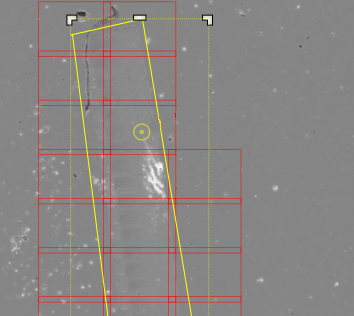
- If required, you can add further support points by using the Add button
 below the Distribute Support Points button. Simply click on the image at the position where you would like to add another support point.
 - Click on Verify Support Points.
- Now you can check if each support point is in focus. You will see the overview image in the right image container and the detail image in the left image container. The verification process will start with the first support point which was set. The current support point is marked with a red crosshair. When you activate Show stage position within the image on the Ribbon Definition tab below the Center Screen Area you will see the current position of the stage in the image as a rectangle with a blue dashed frame.
-
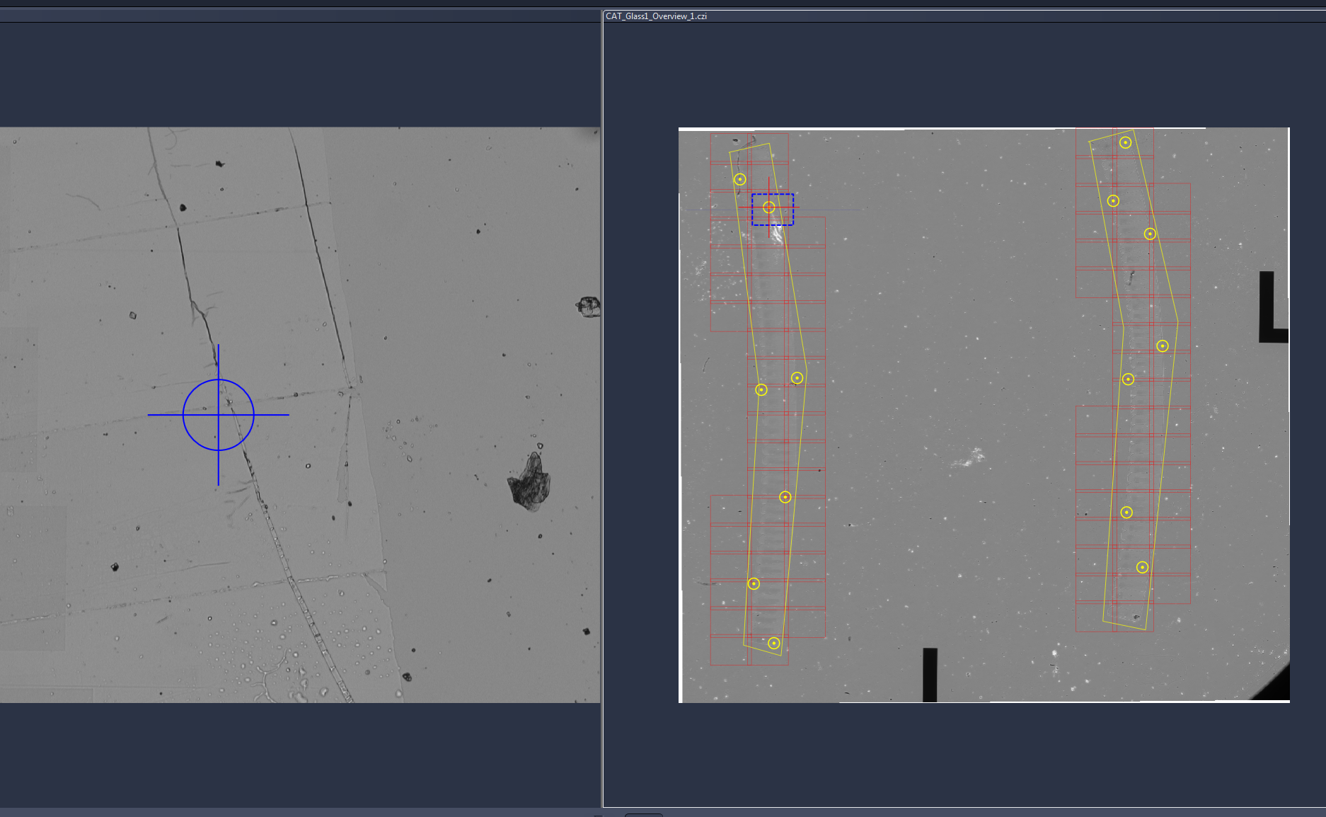
- Hold CTRL on your keyboard and use the mouse wheel to adjust the focus for the corresponding support point.
-
Adjust the focus only by using the mouse wheel. Using the mouse wheel considers the backlash correction. Do not use the focus wheel at the microscope stand.
- When the support point is in focus click on Confirm.
- The software will automatically move to the next support point.
- Repeat the last two steps until you have corrected and verified all support points. At the end of the process you will see the message All points have been verified.
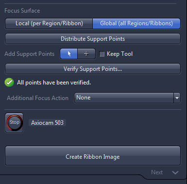
- Click on Create Ribbon Image.
- The ribbon image will be generated. Note that each ribbon will be displayed as one scene.
- Again we recommend clicking on Apply Stitching to remove the offset between the single tile images.
- You have successfully acquired the ribbon image and can now continue to the next step by clicking on Next.
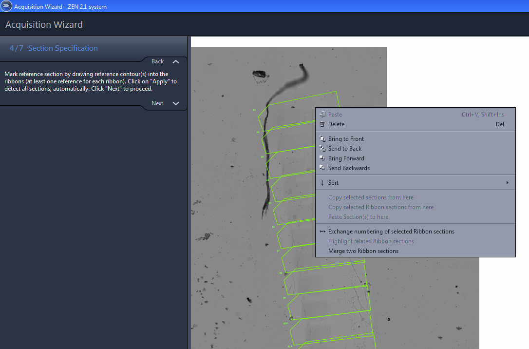
Specifying the Sections
In this step all sections will be identified by using a section detection algorithm. In summary, you have to mark the outline of at least one section on each ribbon. Then the section detection algorithm will detect the sections of the ribbon automatically. If the automatic section detection does not work properly or if not, all sections are detected, you can stamp in the missing sections. It is also possible to edit the shape, location and orientation of the section frames afterwards.
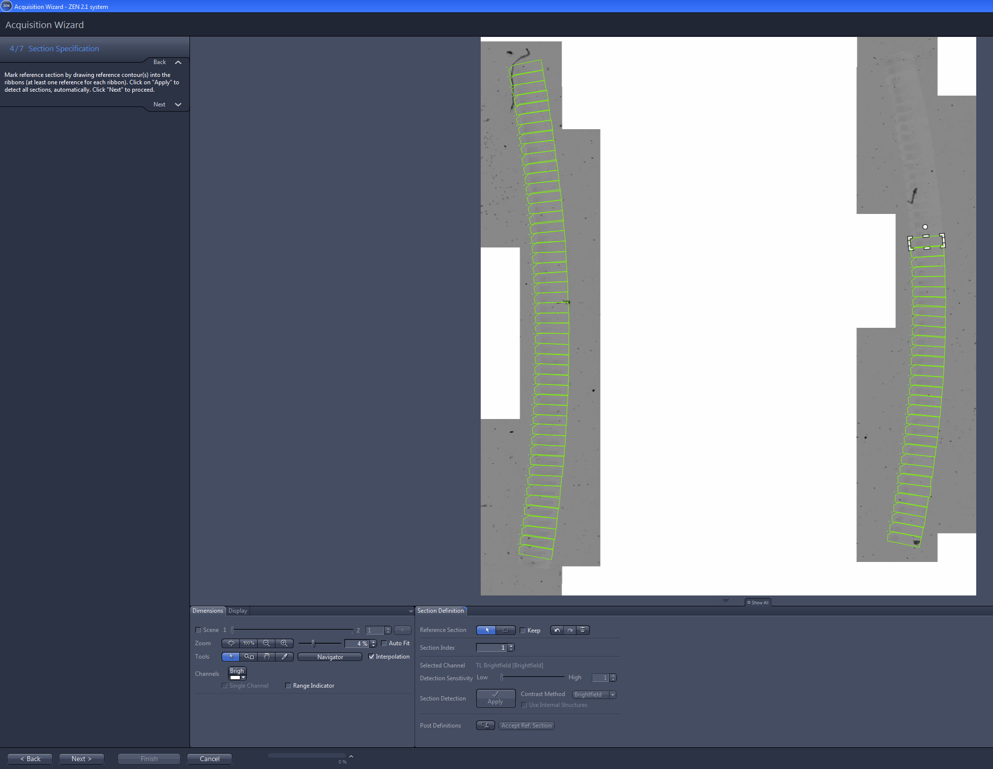
- You are in step 4/7 Section Specification.
- On the Section Definition tab select the Polygon tool.
- Mark the outline of one section in each ribbon. The outlines of these reference contours are displayed in orange color.
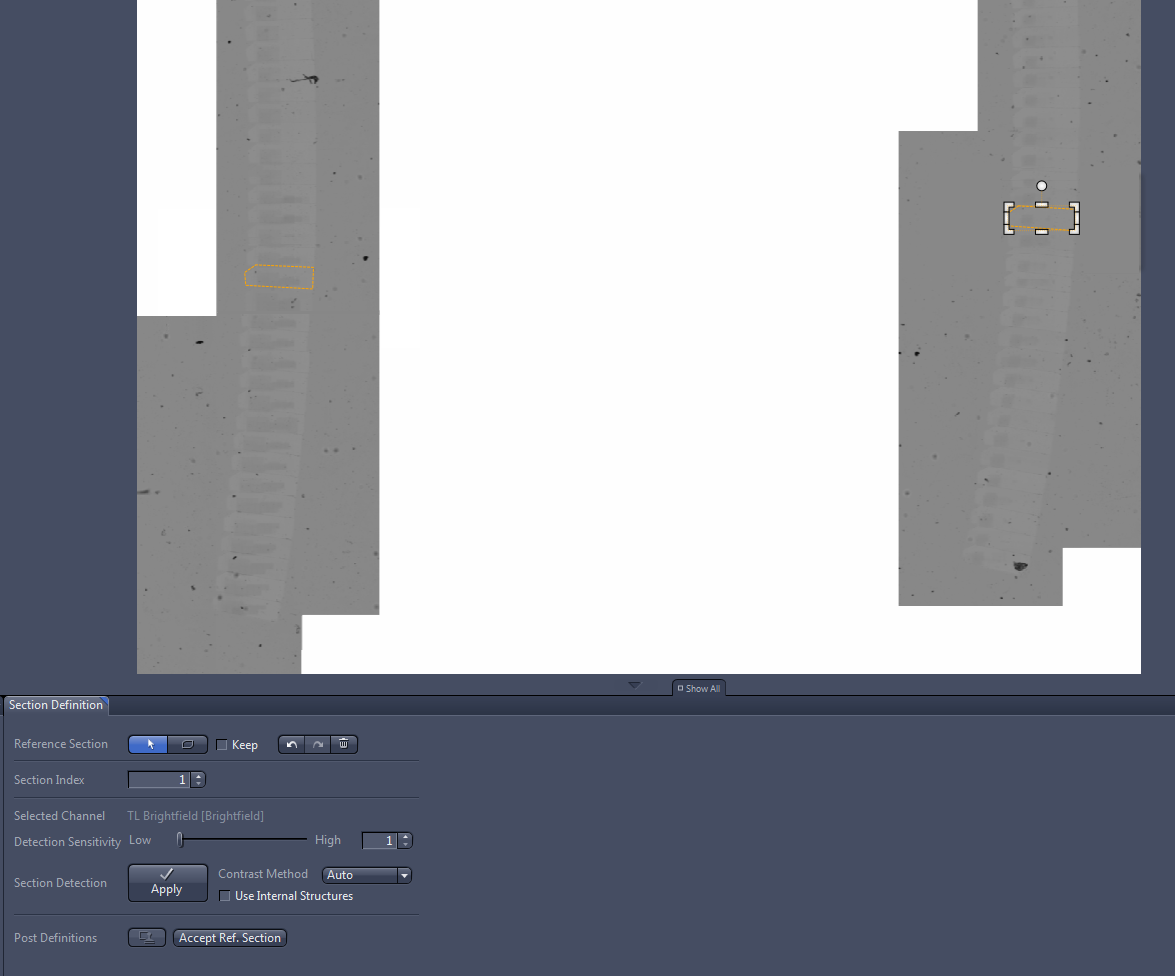
- Click on Apply.
- The software will try to detect the remaining sections automatically. When finished the detected sections appear in green color.
- If not all, sections can be detected, mark the last section which was detected and click on the Stamp tool
 in the Section Definition tab.
 - Stamp in the missing sections so that each section is marked.
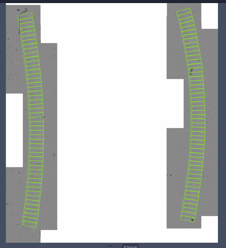
- Please take your time to check the numbering carefully. A correct numbering is prerequisite for a successful alignment of the sections, afterwards. The numbering of the ribbons depends on how you deposited the ribbons during the cutting. To adjust the numbering you have several options available in the context menu. To open the context menu move the cursor over a section and right-click with the mouse.
- If the numbering is correct, proceed to the next wizard step by clicking on Next.
Specifying the ROIs
- You are in step 5/7 ROI Specification.
- On the ROI Definition tab select the desired tool for marking a ROI, e.g. Rectangle or Circle.
- Mark the desired ROIs in one section. Marked ROIs will be displayed in purple color.
-
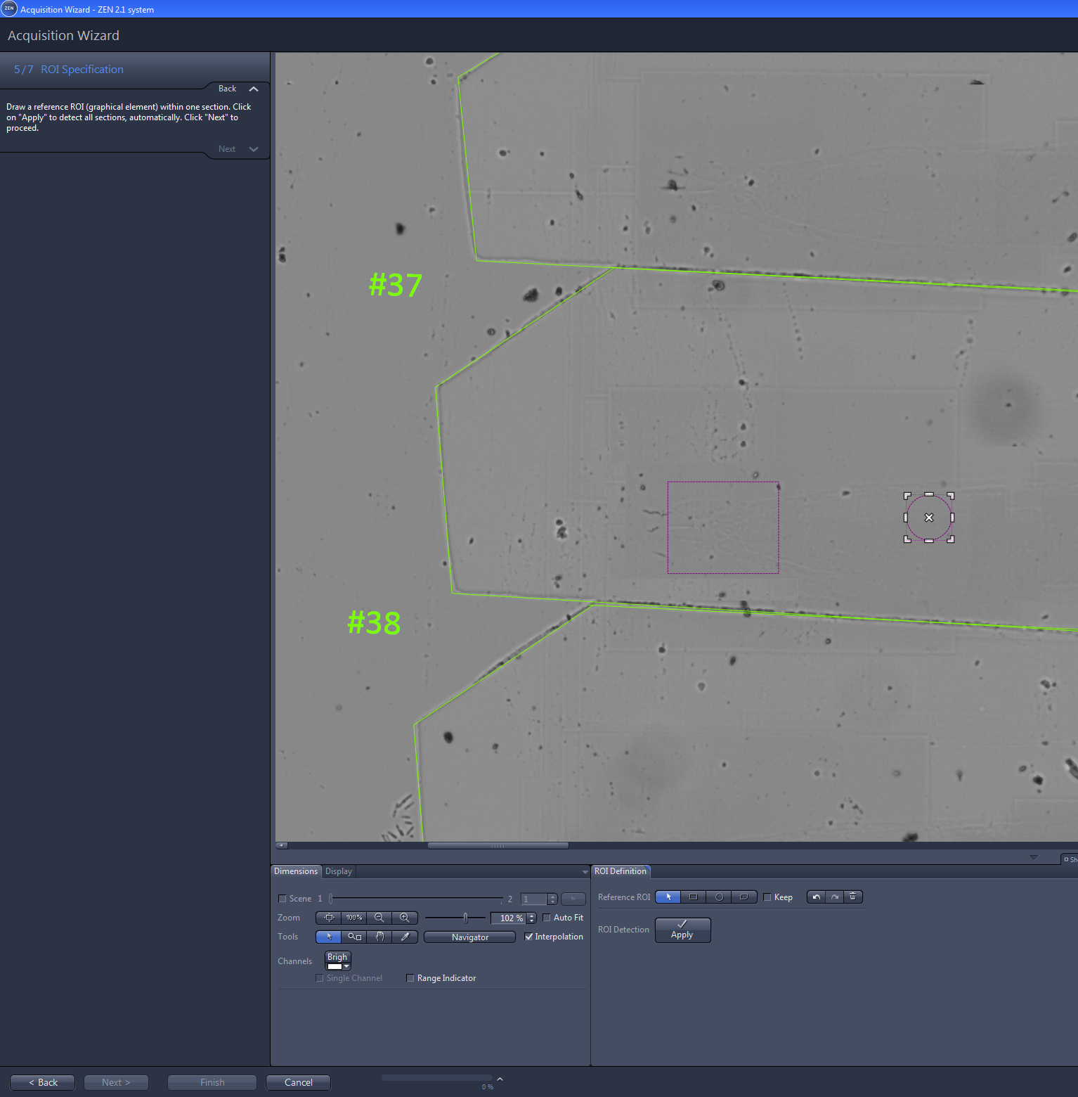
- Click on Apply.
- The software will position the defined region of interests in each section according to section contours. The detected ROIs then appear on each section of the ribbons.
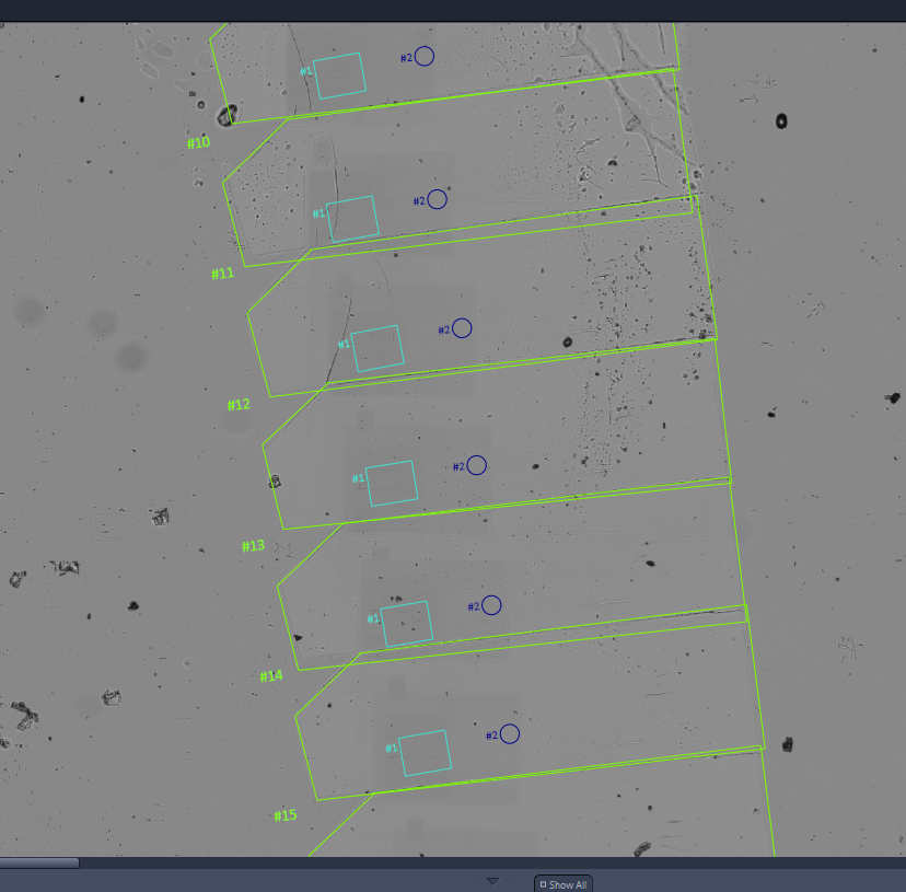
- If the ROIs are detected correctly, proceed with the next wizard step by clicking on Next.
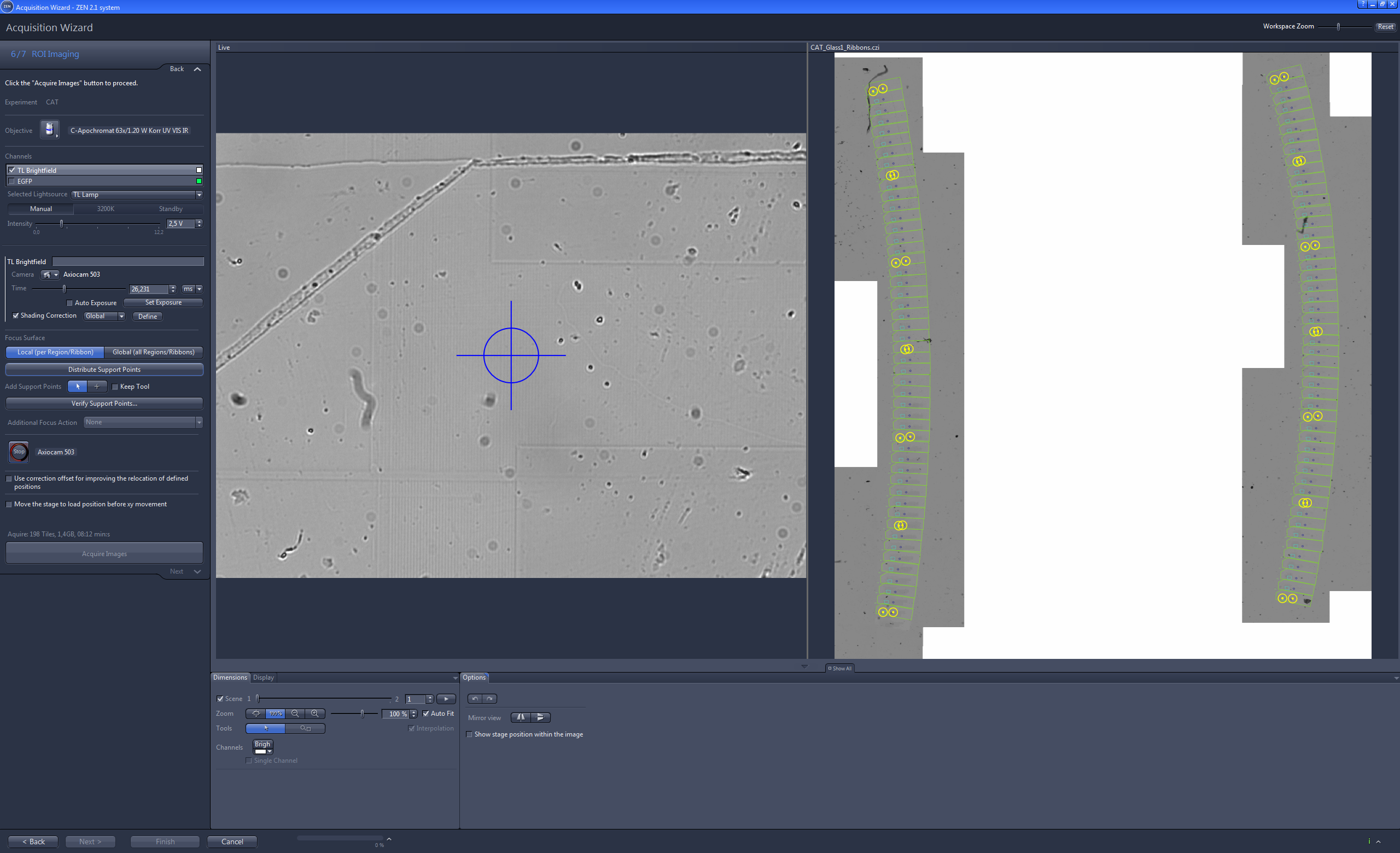
Imaging the ROIs
In this step we will image the ROIs using a high magnification objective and apply a local focus strategy. This will result in very detailed and sharp images of the ROIs which are used for the further processing (e.g. creating Z-Stacks and image correlation with SEM images).
- You are in step 6/7 ROI Imaging.
- Under Objective select an objective with a high magnification, e.g. 63x.
- If you are using fluorescence samples, you can now activate the corresponding fluorescence channel.
- Under Focus Surface select Local (per Region or Ribbon).
- Click on Distribute Support Points.
- According to the step 3 Ribbon Imaging the support points will be distributed automatically. The support points are distributed alternately outside and inside a ROI to guarantee best focusing results.
- Click on Verify Support Points.
- The software will guide you through the process in the same way you were been guided in step 3 Ribbon Imaging.
- If you have verified all existing support points, the message All points have been verified will appear.
- Click on Acquire Images.
- The ROIs will be imaged now. You can use the next step to check each image of the ROIs and re-acquire (re-shoot) images from ROIs which do not fit your expectations. To proceed with the next step click on Next.
Re-Shooting ROIs
This step is basically used for re-acquiring images from ROIs that are out of focus.
- You are in step 7/7 Reshoot.
- Check if the Select Tiles mode is activated. This mode should be selected by default when entering this step.
- You can use the arrows on each side of the image to navigate through the ROI series or the Z-Position slider on Dimensions tab.
- Select an image you want to re-acquire by clicking on it with the left mouse.
- The image will be displayed with a dashed green frame.
- Continue with checking the images and selecting the images you want to re-acquire.
- When you have selected all images to re-acquire click on Acquire.
- The software will move to the first image which you have selected.
- Adjust the focus and click on Snap.
- Click on Replace to replace the old image with the new one.
- The software will automatically move to the next selected image to be re-acquired.
- Continue until you have re-acquired all selected images.
- Click on Finish.
- You have successfully completed the Acquisition Wizard for the light microscope images of your ribbons. Continue with the process described in the next chapter of this guide.