CAT Workflow
Here you will find how-to guides providing an introduction to the CAT module and workflow, starting from general preparations to the acquisition on the LM (light microscope). After the image acquisition we will focus on the image alignment and correlation. As the SEM acquisition is done with Atlas, refer to their documentation for further information about the SEM workflow.
Note that we will not explain how to set up an experiment in detail as this step is beyond the scope of this guide which is focused mainly on the CAT workflow on the LM. Instead read Sample Preparation, where we describe the most important pre-requisites for a CAT experiment. We will not take a look at the further processing of the resulting images as well.
See also
Creating a New Sample
If you have configured your experiment in ZEN (e.g. a multi-channel experiment), the next step is to create and select a sample. When you work with the software for the first time you, have to create a new sample first.
- You are in the Correlative Array Tomography tool.
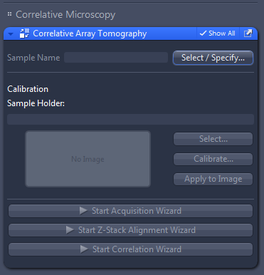
- Click on Select/Specify.
- The Select Sample dialog opens.
- Click on the
 Add button under the List of specified samples.
 - The New Sample dialog opens.
- Enter the necessary sample information: Name, Description, Number of sample carriers, Type of sample carrier and Section thickness.
- Click on OK.
- The dialog closes. You will see the new sample in the List of specified samples.
- Select the new sample from the list and click on OK.
- You have created and selected a new sample.
Note that specifying the correct number of sample carriers is important for the numbering of the ribbons/sections afterwards. The sample information will be stored within the image data and will be used for further image processing and data management.
Selecting the Sample Holder
- You are in the CAT tool.
- In the Sample Holder section click on Select… to open the Select Template dialog and to choose the correlative sample holder you want to use. Different types of correlative holders are available, see Appendix Correlative Sample Holders.
- In the Select Template dialog select the correlative holder you want to use. If you want to use your own sample holders, click on the Add button below the list and follow the instructions in the chapter Defining new sample holder templates.
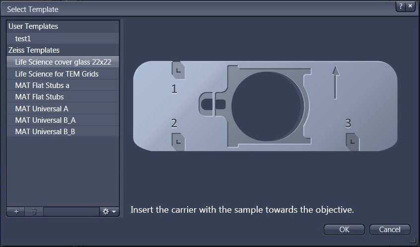
- Click on OK to close the dialog.
- You can now continue with the calibration of the sample holder, as described in the chapter Calibrating the sample holder. Note that the calibration of the sample holder is mandatory to acquire images.
Defining a New Sample Holder Template
With this dialog you can define new correlative holders in addition to the existing holder templates. It is not mandatory to use correlative holders from ZEISS. User-defined correlative holders with 3 fiducial markers can be used as well.
- To open the dialog click on Add in the Select Template dialog. This dialog can be opened via the Shuttle & Find tool.
- The New Template dialog opens.
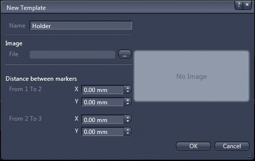
- Type in a name for the new holder or sample carrier. An image of the new holder can be loaded as well.
- Insert the distances (in millimeters) between the first and the second marker and between the second and third marker.
- The distances can be determined using the Stage Control dialog accessible via the Light Path tool in Right Tool Area tab. We recommend doing this before starting the New template dialog. Write down the distances to be prepared to enter them within the New Template dialog.
- Activate the live view in the Center Screen Area by clicking on the Live button in the Locate tab.
- Navigate the stage manually to the calibration marker on the sample holder by means of the joystick and note the x/y-coordinates of the marker.
- Repeat this procedure for all three markers and calculate the distances between marker 1 and marker 2 and between marker 2 and marker 3, respectively.
Aligning the Z-Stack Image
The wizard contains the following 6 steps:
- Image Import
- Pre-Processing
- Image Review
- Alignment
- Manual Correction
- Final Image Creation
- In the CAT tool click on Start Z-Stack Alignment Wizard.
- You will see the first step Image Import of the wizard.
- Click on Load Image and select the acquired Z-Stack image from the file system. In our example we choose the LM image. The same process has to be performed for the SEM image afterwards.
- You will see the Z-Stack image in the center screen area.
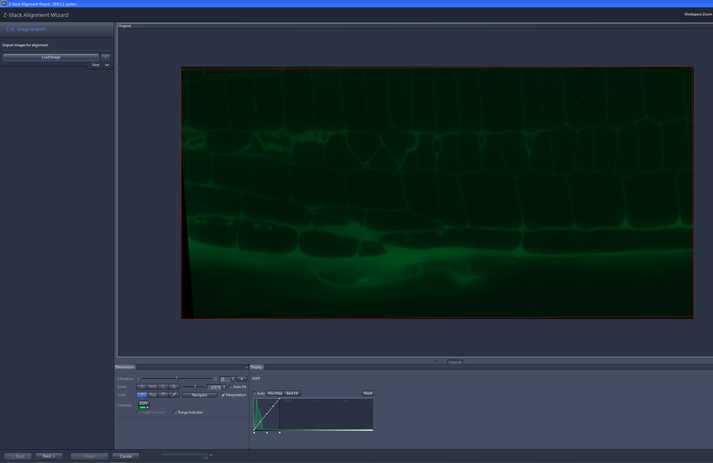
- Click on Next.
- You will see step 2/6 Pre-Processing.
- If your image is a tile image, click on Apply Stitching to correct the offset between the individual tiles.
- If your image is a SEM image, click on Histogram Equalization to adjust the image display.
- Click on Next.
- You will see step 3/6 Image Review. Note that in this step no image acquisition is possible. You can just replace an image by the next or previous image of the Z-Stack.
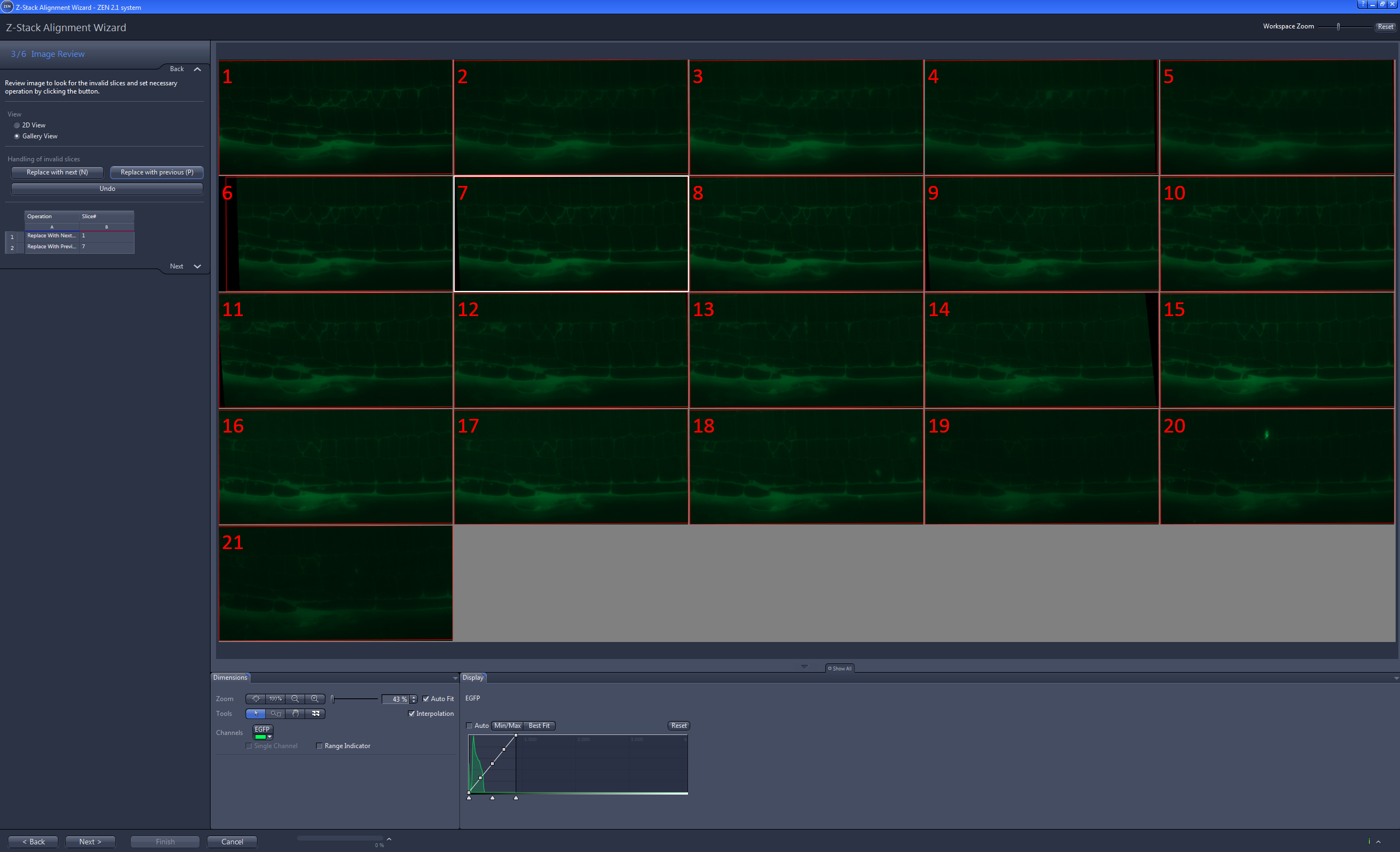
- Select the image to be replaced by clicking on it with the mouse and click on Replace with next or Replace with previous. Alternatively, you can press the N or the P key. Note that the table of the replaced image will not be saved.
- Click on Next.
- You will see step 4/6 Alignment.
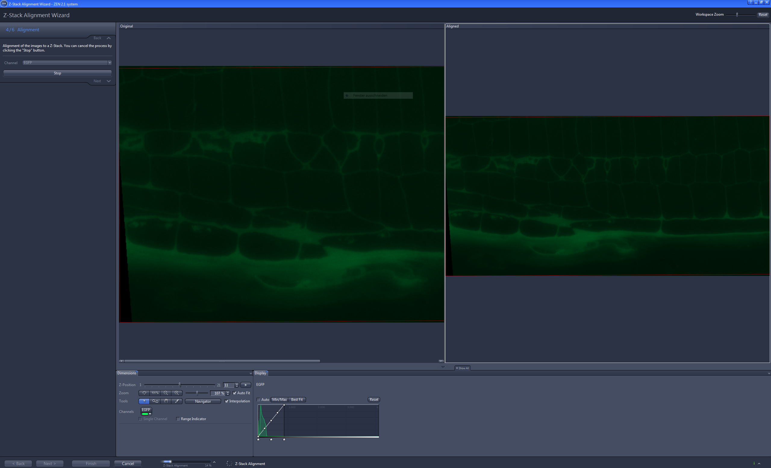
- If you have acquired a multi-channel image, select the reference channel from the Channel list.
- Click on Start Alignment.
- The alignment of the Z-Stack image will be performed automatically. After the alignment you will see the original Z-Stack image in the left image and in the right image you will see the aligned Z-Stack image.
- Click on Next.
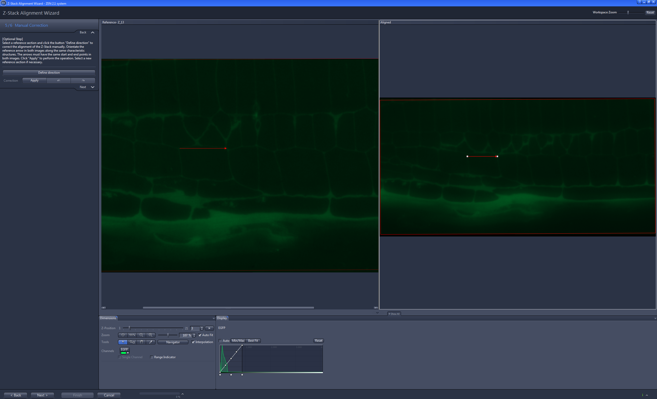
- You will see step 5/6 Manual Correction.
- If you browse through the Z-Stack by using the Z-Position slider and you still realize a shift between the single Z-Stack images, you can perform a manual correction of the single Z-Stack images. Therefore continue as follows:
- Click on Define direction.
- A red arrow will appear in the right and in the left image.
- Place the arrow in the left image at a prominent structure in the image which is easy to recognize through the full Z-Stack.
- Select the right image and browse through the Z-Stack by using the Z-Slider on the Dimensions tab.
- When you realize a shift in an image, adjust the arrow in the right image so that it matches with the prominent structure marked with the arrow in the left image. Note that you have to check and adjust the arrow for each image of the Z-Stack which does not match the position.
- Click on Apply.
- The correction will be applied. If you want to correct the Z-Stack at another position, simply repeat the procedure with another prominent structure. Of course you can undo and redo actions by using the Undo/Redo buttons.
- Click on Next.
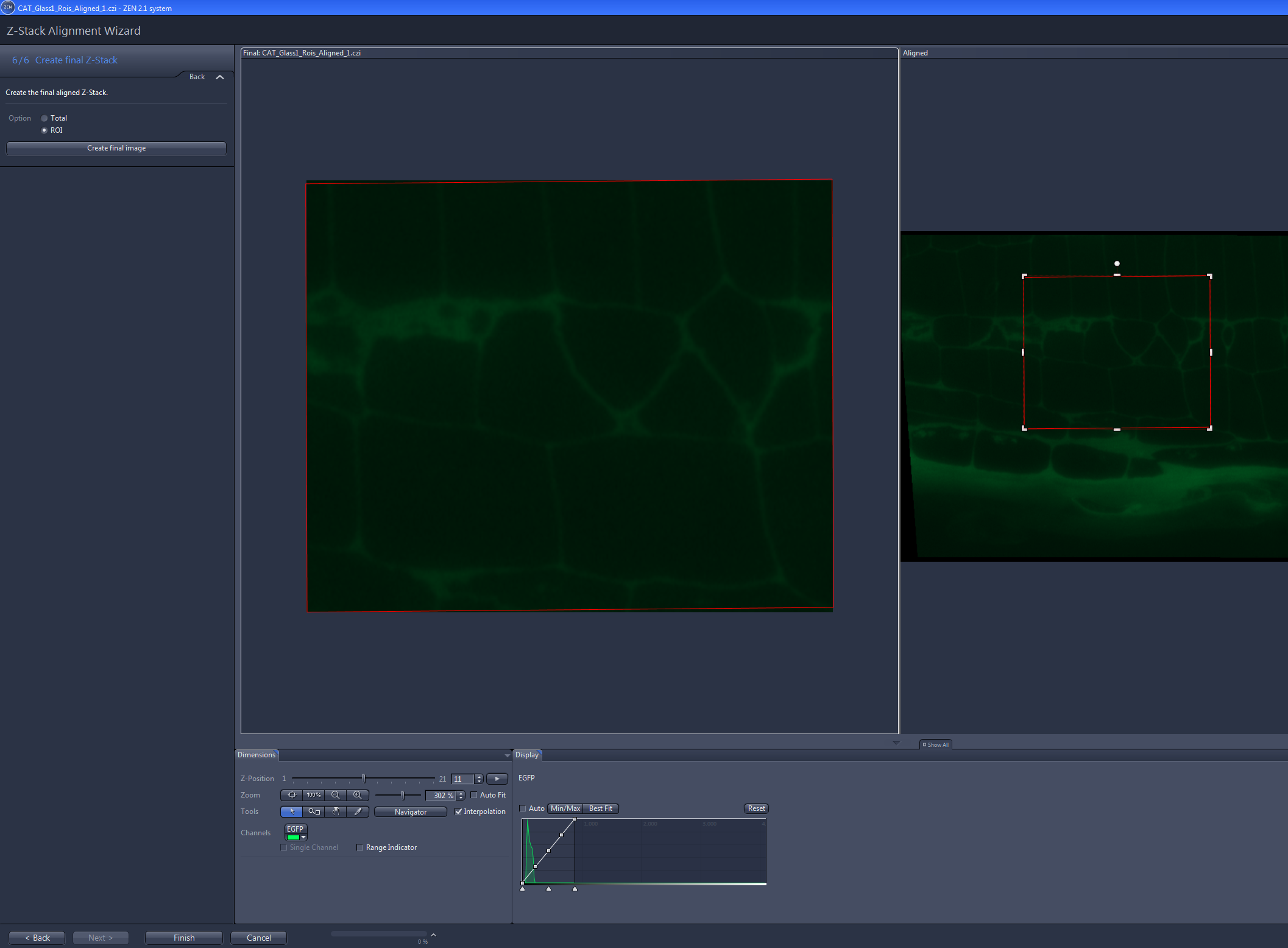
- You are in step 6/6 Create final Z-Stack.
- If you want to create the Z-Stack image from the complete image, select Total and click on Create final image.
- If you want to create the Z-Stack image from the marked ROIs, select ROI. Note that you can adjust the marked ROI in its size and position here. If you have marked more than one ROI, you can switch between the ROIs by using the Scene slider on Dimension tab.
- Click on Create final image.
- You have successfully aligned and created the Z-Stack image. Of course you have to repeat the process for the SEM image that was acquired.
Correlating the LM and SEM images
With the correlation wizard you can correlate the images of the LM and SEM. Note that we do not recommend to perform this correlation for SEM images acquired with the Atlas Array Tomography module. The wizard contains the following 4 steps:
- Import Z-Stacks
- Correlation
- Manual Correction
- Create Final Correlation Image
- In the CAT tool click on Start Correlation Wizard.
- You will see the first step Import Z-Stacks.
- Click on Left Container to load the aligned z-stack image from the SEM.
- Click on Right Container to load the aligned z-stack image from the LM.
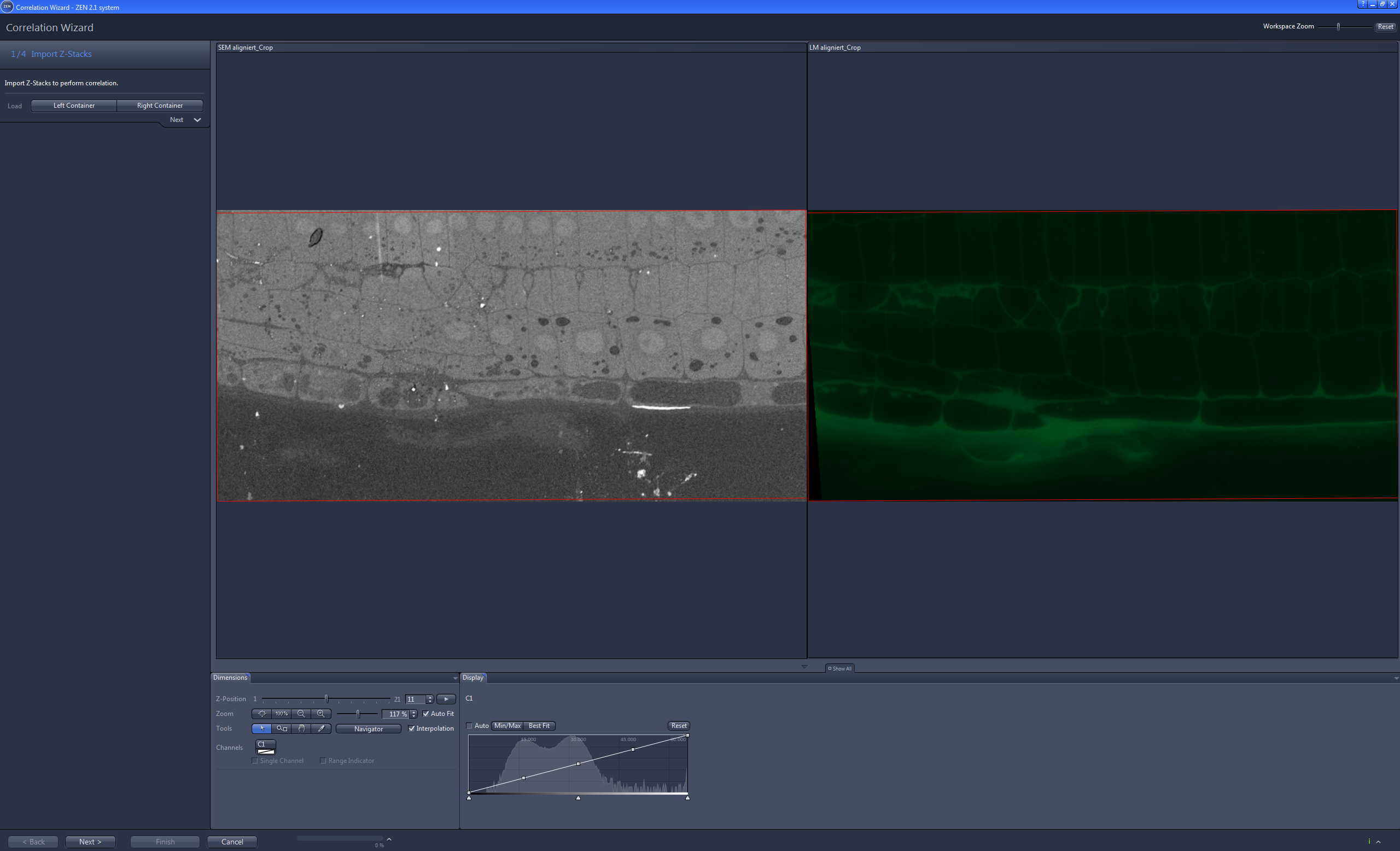
- Click on Next.
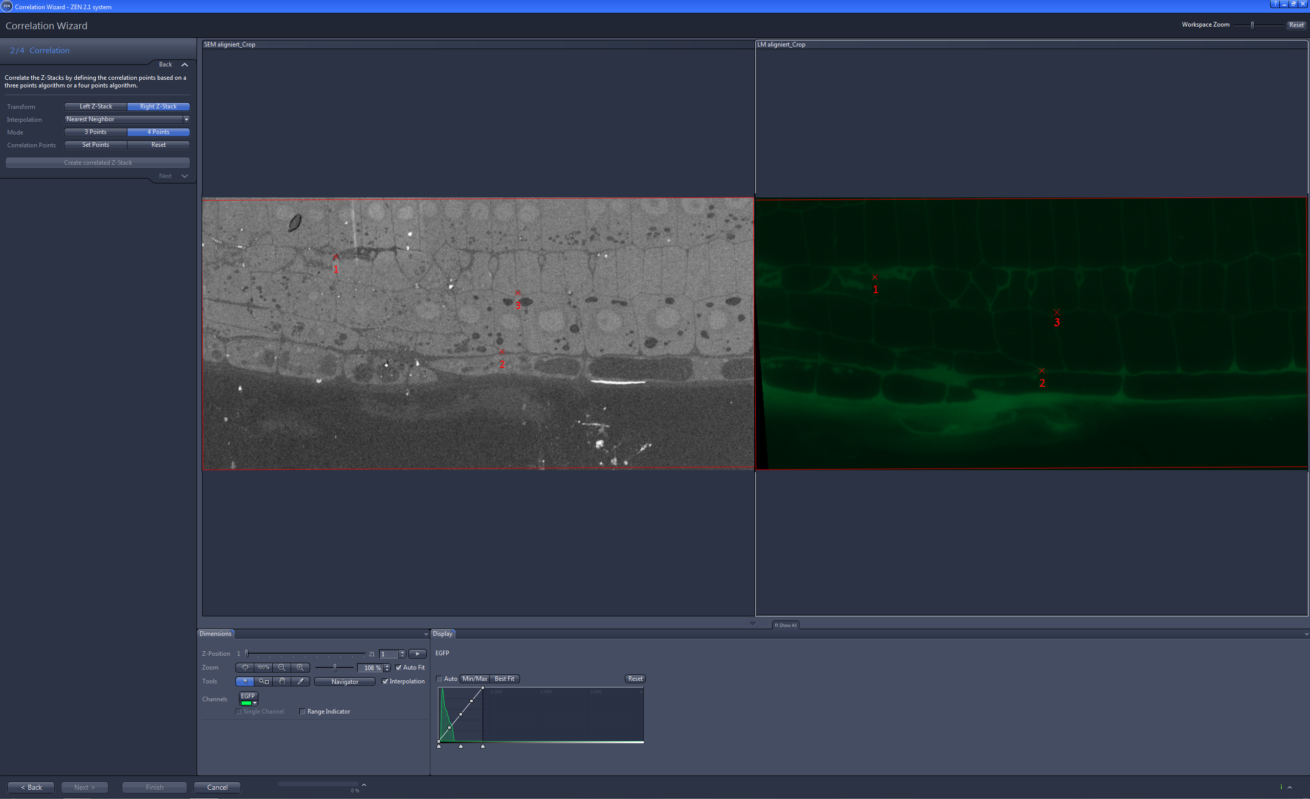
- You will see step 2/4 Correlation.
- Under Transform decide whether you want to transform the Left Z-Stack into the Right Z-Stack or vice versa.
- Under Mode select 4 Points.
- Click on Set Points.
- Set the first 3 correlation points in the first Z-Stack image of the left image.
- Set the corresponding 3 correlation points in the first Z-Stack image of the right image.
- After the third point in the right image was set, the software automatically jumps to the last Z-Stack image.
- Set the fourth correlation point in the left image first and then set it in the right image.
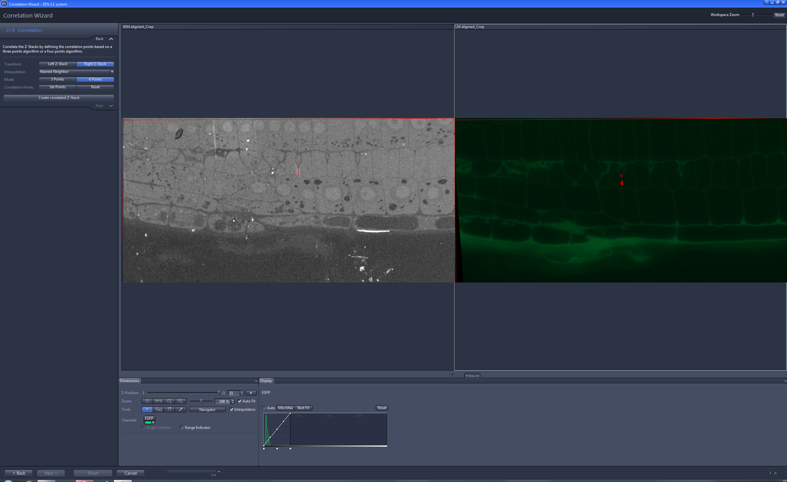
- Click on Create correlated Z-Stack.
- The correlated Z-Stack image will be generated and displayed in a separate image container.
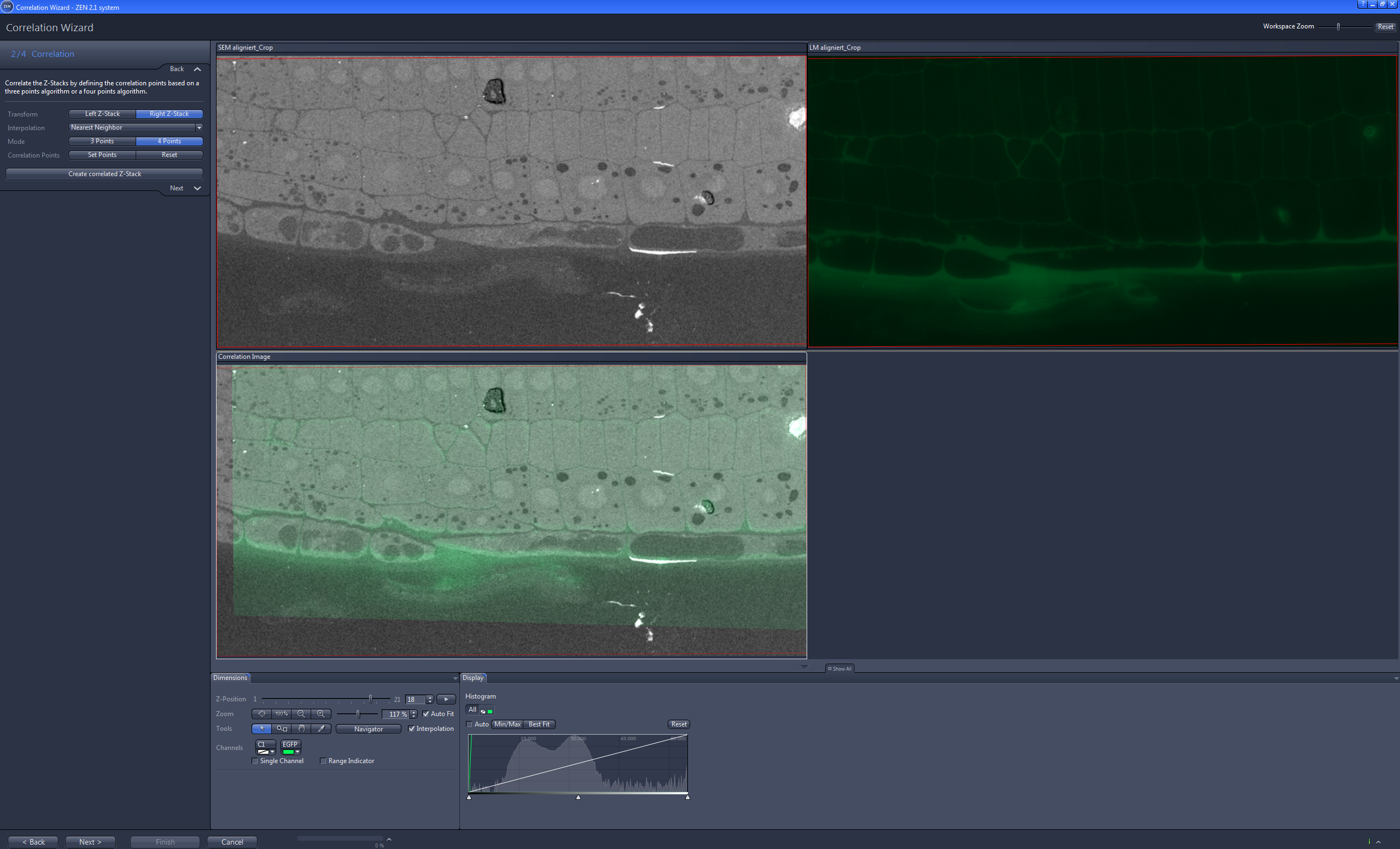
- Click on Next.
- You will see step 3/4 Manual Correction.
- In this step you can manually correct the alignment of the images by moving and/or rotating the images according to each other. To rotate the image use the handle at the top of the image frame. To move the image simply left click on the image and hold the mouse button pressed while moving the image.
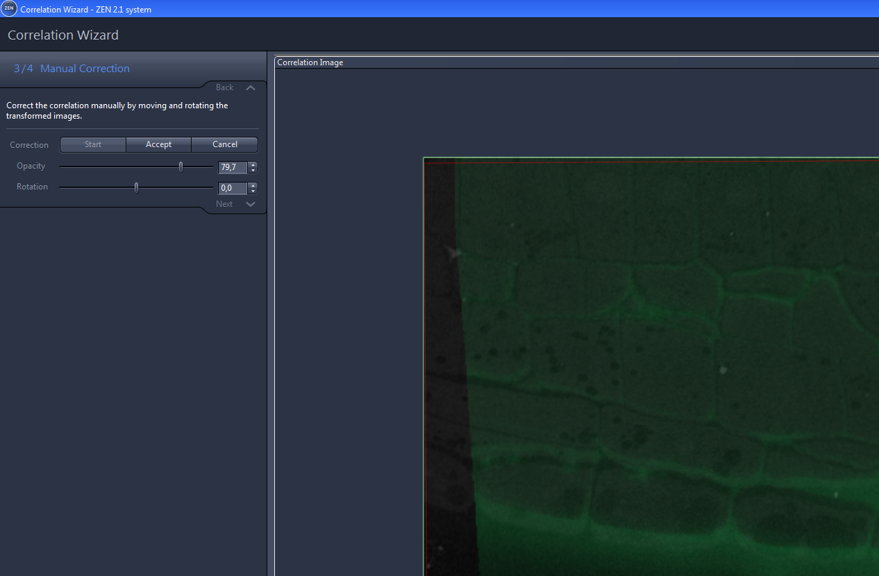
- If you finished the alignment of an image click on Accept. You can browse through the correlated Z-Stack images by using the Z-Position slider in the Dimension tab.
- Click on Next.
- You will see step 4/4 Create Final Correlation Image.
- Click on Create Final Z-Stack.
- The correlated Z-Stack image will be created.
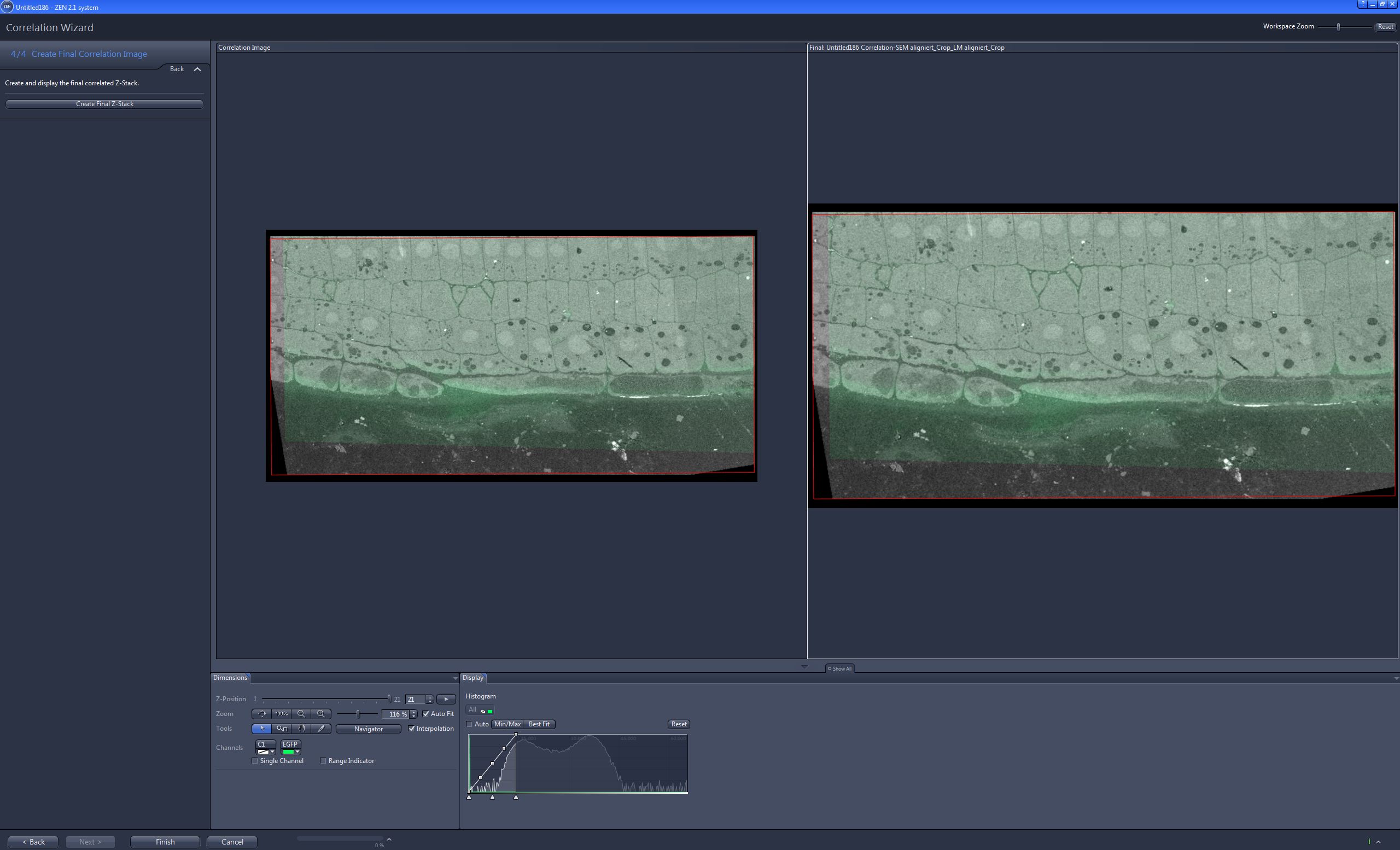
- Click on Finish to exit the wizard.
- You have successfully created a correlated Z-Stack image.