Correlative Array Tomography (CAT)
This module enables you to perform automated imaging of ultra-thin serial sections (ribbons) using the light- and scanning electron microscope. After calibration of the sample carrier and detection of the sections, regions of interest can be defined manually in a single section that will be automatically propagated to all sections. The selected regions of interest can then be imaged with different contrast methods and magnifications using the LM.
On the SEM, the regions of interest defined on the LM are then imaged automatically after loading the image from the LM. The corresponding 2D image sequences recorded by the LM and SEM are aligned into a 3D z-stack using the integrated alignment algorithm of the Correlative Array Tomography module and the Atlas Array Tomography module. The resulting 3D z-stacks can then be used for correlation.
For the correlative workflow, ZEN with the CAT module has to be installed on the widefield system, and the Atlas Software with the Array Tomography module has to be installed on the SEM. For a detailed how-to guide of the workflow, see CAT Workflow.
The software module can be used with ZEISS widefield microscopes. Besides the CAT tool the module offers four wizards. Detailed descriptions of the functions of the tools and wizards can be found in the linked sections.
- Correlative Array Tomography tool, see CAT Tool.
- Calibration Wizard, see Sample Holder Calibration Wizard.
- Acquisition Wizard, see Acquisition Wizard.
- Z-Stack Alignment Wizard, see Z-Stack Alignment Wizard.
- Correlation Wizard, see Correlation Wizard.
See also
Basics of Array Tomography
Array Tomography is a volumetric microscopy method employed to visualize and reconstruct 3D images of serial sections. Tissue samples or cells embedded in resin are cut into consecutive sections with an ultramicrotome and collected onto a sample carrier (e.g. cover glass). The sequence of the sections determines the z-position and allows the reconstruction of the 3rd dimension. Therefore the z-resolution of the resulting 3D data set is determined by the thickness of the section.
The correlation of scanning electron microscope (SEM) data especially with an image acquired using a fluorescence light microscope (LM), enables the visualization of fluorescently labeled biological structures in their ultrastructural context not only in 2D but now in 3D with the ZEN Correlative Array Tomography module.
Sample Preparation
Type of Sample Carrier/Cover Glasses
We recommend cover glasses coated with Indium tin oxide and fiducials. Indium tin oxide minimizes charging effects in the scanning electron microscope. Cover glasses with fiducials enables additional preparation steps after imaging the sample with the light microscopes and before imaging with a scanning electron microscope.
Deposition of Serial Sections on the Cover Glass
- Sequence of serial sections
During serial sectioning, make sure that you know the sequence of the ribbons as well as the start and the end point of the ribbons. - Positioning of serial sections on a cover glass
It is important to position the serial sections in the center of the cover glass. If the sections are too close to the edge of the cover glass, it might happen that the objective touches the sample carrier during the image acquisition. This might happen particularly for immersion objectives. The consequence will be that the focus map is not calculated in the correct way or images are out of focus. - More than one ribbon (serial section) on a cover glass
Take care that the single serial sections are not in close contact to each other, this might confuse the numbering algorithm of the software and creates a wrong numbering.
Pre-Settings (Light Microscope)
Before you can work with the CAT module, you have to check the following settings on the light microscope system (hardware and software settings). In general, the system is calibrated by a service technician but we recommend checking the settings again, especially when you have changed components, e.g. objectives or filter cubes. As these general settings are not described here in detail, please ask your service technician, or read the ZEN Online Help.
- Check Parcentricity and Parfocality
Note that the calibration of parcentricity and parfocality has to be done at the TFT display of the microscope. - Check Camera Orientation and Stage Movement
Before checking the stage movement the correct camera orientation always has to be set first. The camera orientation should match your view through the ocular of the microscope. If this is not the case, you can change the camera orientation in the Camera tool.
To check the stage movement we recommend acquiring a tiles image and check if the tiles are put together correctly. If this is not the case, you have to close ZEN software and open the MTB 2011 software. There you must change the stage inversion in the configuration list under Motorized Stage. - Perform Shading Correction
Before starting the CAT workflow a shading correction has to be performed in ZEN software. Please read the corresponding chapter in the ZEN Online Help.
Experiment Settings
For working with the CAT module you need to set up an experiment in the ZEN software first. As this is already described in the ZEN Online Help, we will focus here on the most important settings which are essential for the CAT workflow:
- In the menu Tools > Options > Acquisition > Acquisition tab the checkbox Enable Advanced Imaging Setup must be activated.
- In the Imaging Setup tool Show All must be activated.
- In the Imaging Setup tool Advanced Imaging Setup must be selected.
- In the Imaging Setup tool in the light path display the following settings have to be adjusted:
- The Microscope Manager must be excluded from all settings. To exclude a setting, click on the icon of the component/setting. You will see a menu where you can activate/deactivate the checkbox Include in this Setting. If the checkbox is not activated, the component/setting is excluded from the selected setting. Note that you have to select each Before/After setting and check if the components are excluded or included and adjust it accordingly.
- The TL/RL Switch must be excluded from all settings.
- All TL/RL Shutters in the light path must be included in all settings. Note that icons of included settings are highlighted in blue color.
- All light sources (TL/RL) within the light path must be included in all settings.
- The light intensity of the light sources for all settings must be the same (e.g. 2V).
- In general for the Before Experiment and After Experiment settings adjust the following:
- All Shutters must be closed.
- Example for Phase Contrast settings:
- For the Before TL Phase settings adjust the following:
- - The TL Shutter must be opened.
- - The RL Shutter must be closed.
- For the After TL Phase adjust the following:
- - The TL Shutter must be closed.
- - The RL Shutter must be closed.
- Example for one Fluorescence Channel (here DAPI) settings:
- For the Before DAPI settings adjust the following:
- - The TL Shutter must be closed.
- - The RL Shutter must be opened.
- For the After DAPI adjust the following:
- - The TL Shutter must be closed.
- - The RL Shutter must be closed.
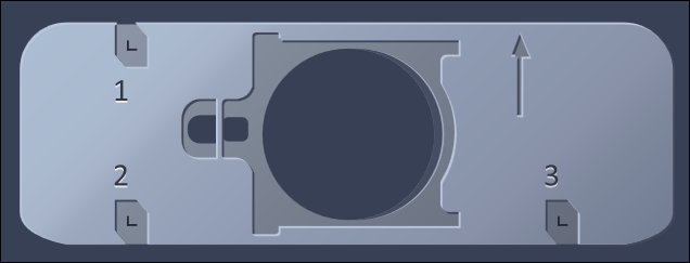
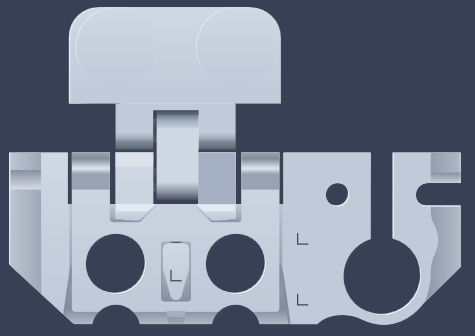
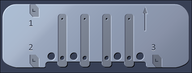
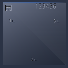
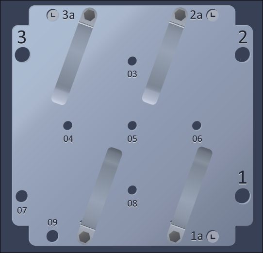
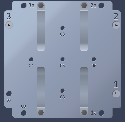
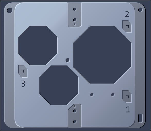
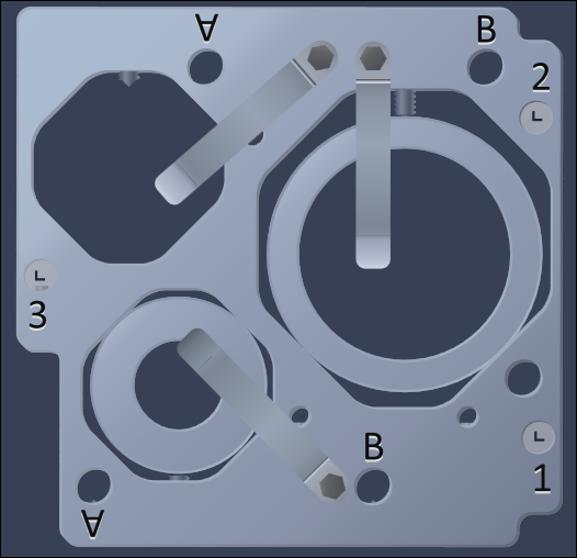
Correlative Sample Holders
|
Name |
Image |
|---|---|
|
Life Science cover glass 22 x 22 |
|
|
Life Science Cryo Holder |
|
|
Life Science for TEM Grids |
|
|
Cover glass with fiducials 22 x 22 |
|
|
MAT Flat Stubs A |
|
|
MAT Flat Stubs |
|
|
MAT Universal A |
|
|
MAT Universal B_A |
|
|
MAT Universal B_B |
|