PSF Settings Tab Apotome Plus (adjustable)
All key parameters for generating a theoretically calculated Point Spread Function (PSF) are displayed on this tab.
Usually, images (with file type *.czi) that have been acquired with ZEN automatically contain all microscope parameters, meaning that you do not have to configure any settings on this tab. Therefore, most parameters are grayed out in the display. It is possible, however, that as a result of an incorrect microscope configuration values may not be present or may be incorrect. You can change them here. The correction of spherical aberration can also be set here.
|
Parameter |
Description |
|---|---|
|
Get PSF Parameters from Input Image |
Activated: The parameters of the PSF are taken directly from the input image and the respective parameters are displayed and grayed out (not editable). This is the default setting. Deactivated: Enables you to manually change the PSF parameters. |
Microscope Parameters Section
The most important microscope parameters for PSF generation that are not channel-specific are displayed in this section.
If you enter incorrect values, this can lead to incorrect calculations. If the values here are obviously wrong or values are missing, check the configuration of your microscope system.
|
Parameter |
Description |
|---|---|
|
NA Objective |
Displays the numerical aperture of the objective. |
|
Immersion |
Displays the refractive index of the immersion medium. Note that this can never be smaller than the numerical aperture of the objective. You can make a selection from typical immersion media in the dropdown list next to the input field. |
|
Scale Lateral |
Displays the geometric scaling in the X/Y direction. |
|
Scale Axial |
Displays the geometric scaling in the Z direction. |
Advanced Section
Only visible if the Show All mode is activated.
|
Parameter |
Description |
|
|---|---|---|
|
Phase Ring |
If you have acquired a fluorescence image using a phase contrast objective, the phase ring present in the objective is entered here. This setting has significant effects on the theoretical Point Spread Function (PSF). |
|
|
PSF Generation |
Selects the model for calculating the PSF. |
|
|
– |
Scalar Theory |
The wave vectors of the light are interpreted as electrical field = intensity and simply added. This method is fast and is sufficient in most cases (default setting). |
|
– |
Vectorial Theory |
The wave vectors are added geometrically. However, the calculation takes considerably longer. |
|
Z-Stack |
This field can only be changed if it was not possible to define this parameter during acquisition, e.g. because the microscope type was unknown. It describes the direction in which the z-stack was acquired. Note that this setting is only relevant, if you are using the spherical aberration correction. |
|
|
– |
Descending |
The z-stack descends away from the objective. |
|
– |
Ascending |
The z-stack ascends towards the objective. |
Aberration Correction Section
Only visible if the Show All mode is activated.
Here you can select whether you want spherical aberration to be taken into account and corrected during the calculation of the PSF. As with the other PSF parameters, most values are extracted automatically from the information about the microscope that is saved with the image during acquisition. The input option is therefore inactive.
|
Parameter |
Description |
|---|---|
|
Enable Correction |
Activated: Uses the correction function. All options are active and can be edited. |
|
Embedding Medium |
Select the used embedding medium. |
|
Refractive Index |
Displays the refractive index of the selected embedding medium. Enter the appropriate refractive index if you are using a different embedding medium. |
|
Manufacturer |
Displays the manufacturer, if known. |
|
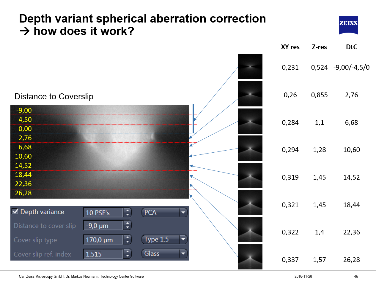
Depth Variance |
When Aberration correction is activated, it is also possible to enable the creation of depth variant PSFs. This method allows for dramatic improvements in image restoration of thicker samples by creating axially variant theoretical PSFs as a function of the distance to the coverslip and the refractive index of the mounting medium. Activated: Uses depth variant aberration correction. In the spin box edit field you can define how many PSFs should be generated. The more PSFs you create, the better the results, but selecting many PSFs increases the processing time. You should choose at least 3 PSFs. In the dropdown list you can choose between the PCA method (Primary Component Analysis, M. Arigovindan et al., 2005, IEEE Transactions on Image Processing 14. nr. 4 p.450ff) which is best suited for constrained iterative and fast iterative method and the Strata method (Myneni and Preza, Frontiers in Optics 2009, Optical Society of America, paper CThC4.), which is best for regularized inverse filter and Richardson Lucy iterative deconvolution. |
|
Distance to Cover Slip |
Displays the distance of the acquired structure from the side of the cover slip facing the embedding medium. Half the height of the z-stack is assumed as the initial value for the distance from the cover slip. The value can be corrected if this distance is known. If possible, this distance should be measured. Note: Use Ortho View and the Distance Measurement option to define the distance of the sample to the coverslip. It is also important to estimate the position of the glass/embedding medium interface as precise as possible. If the z-stack extends into the coverslip, the determined range of the stack which reaches into the glass should be entered as a negative value. Example: Z-stack is 26 µm thick, glass/medium interface is positioned at 9 µm distance from the first plane of the stack. Resulting value for Distance to cover slip: - 9.0 µm. |
|
Cover Slip Type |
Commercially available cover slips are divided into different groups depending on their thickness (0, 1, 1.5 and 2), which you can select from the dropdown list. Cover slips of the 1.5 type have an average thickness of 170 µm. In some cases, however, the actual values can vary greatly depending on the manufacturer. For best results the use of cover slips with a guaranteed thickness of 170 µm is recommended. Values that deviate from this can be entered directly in the input field. |
|
Cover Slip Ref. Index |
Selects the material that the cover slip is made of. The corresponding refractive index is displayed in the input field next to it. |
|
Working Distance |
Displays the working distance of the objective (i.e. the distance between the front lens and the side of the cover slip facing the objective). The working distance of the objective is determined automatically from the objective information, provided that the objective was selected correctly in the MTB 2011 Configuration program. You can, however, also enter the value manually. |
|
Override |
Only active if Enable Correction is activated. |