Tiles Tool
The basic Tiles tool is only visible if you have a motorized stage configured with your microscope. The Tiles Advanced Setup and many other functions are only available if you licensed this functionality and activated it in the Toolkit Manager. Additionally, you must activate the corresponding checkbox on the Acquisition tab in the Experiment Manager. This tool is part of the basic license for LSM.
In the Tiles tool you configure the acquisition of images that consist of several image fields. Therefore you define Tile Regions or Positions. In addition you can set up focus surfaces and sample carrier templates here.
The Tiles tool is located in the Left Tool Area under Multidimensional Acquisition.
|
Parameter |
Description |
|---|---|
|
Show Viewer |
Only available if you have the license for the Tiles & Positions functionality. Opens the Tiles Advanced Setup view in the Center Screen Area. |
The Sample Carrier, Focus Surface and Options sections are only visible if the Show All mode is activated.
If you have no license for the Tiles & Positions module you will only find Tile Regions, Positions and Options sections here.
The different sections of the tool are described in the next chapters.
Tile Regions Section
Here you can define the desired tile regions and add it to the image.
Note: The first section with controls is only visible if you have no license for the Tiles & Positions module. With a license, these controls are selected from the Left Toolbar in the Tiles Advanced Setup.
|
Parameter |
Description |
|
|---|---|---|
|
Contour |
This parameter is only visible if the Show All is activated. Here you select the shape or contour of the tile region that you are adding. Simply click on the corresponding button to select the desired contour. The selected contour is highlighted in blue color. |
|
|
- |
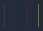
Rectangle |
If selected, you can create rectangular tile regions. |
|
- |
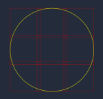
Circle |
When selected, you can create circular tile regions. |
|
Mode |
||
|
- |
Tiles |
If selected, you have to enter the number of tiles as a reference for the size of the tile region. |
|
- |
Size |
If selected, you have to enter the size as a reference for the size of the tile region. |
|
- |
Stake |
If selected, you can define a tile region by the placement of at least two markers (user defined X/Y stage coordinates). If you want to modify the tile region (expand/reduce) you have to adjust the tile region to the desired size. To complete the tile region press Done. Circular or rectangular tile region can be created in this manner by selection of the appropriate contour. |
|
- |
Add |
Adds the tile region to the image. The added tile region will also appear in the Tile Regions List and is activated for acquisition. Added tile regions are displayed in the form of red grids in the stage view of the Advanced Tiles Setup. |
Tile Region List Options
|
Parameter |
Description |
|
|---|---|---|
|
Tile Regions List |
Displays the added tile regions. The list contains the following columns: |
|
|
- |
Checkbox |
Activates the relevant list entry for acquisition. |
|
- |
Name |
Here you can edit the name of the tile region. |
|
- |
Category |
Displays the category of the tile region. Categories can be defined in the view options of the advanced tiles setup on the properties tab. |
|
- |
Tiles |
Displays the number of tiles of the tile region. |
|
- |
Z |
Displays the z-position of the tile region. |
|
- |
Size |
Displays the size of the tile region along its x and y axes in micrometers. |
|
Up |
With the Up/Down buttons you can shift the selected list entry one position up or down in the tile regions list. This allows you to modify the acquisition order. Note that the order in the list will only be respected if the sorting of tile regions/ positions is deactivated in the Options section (Stage Travel Optimization)! |
|
|
|
Deletes the selected list entry. |
|
|
|
If you click on the button, you see the following options: |
|
|
- |
Set Current Z for Selected Tile Regions |
Sets the current z-position for all selected tile regions. |
|
- |
Set Current X/Y/Z for Selected Tile Regions |
Sets the current X/Y/Z-Position for all selected tile regions. |
|
- |
Delete |
Deletes the current tile region. |
|
- |
Delete All |
Deletes all tile regions. |
|
- |
Activate |
Activates the current tile region for acquisition. |
|
- |
Deactivate |
Deactivates the current tile region for acquisition. |
|
- |
Unlock |
Unlocks the current tile region. The tile regions or positions are only locked if created in carrier mode. |
|
- |
Unlock All |
Unlocks all locked tile region. |
|
- |
Sort |
By Center Position (Y -> X) sorts all tile regions according to their overall Y position. |
|
- |
Convert to Positions… |
Converts a selected tile region into Positions or a Position Array. |
|
Properties Tile Region |
Only visible if you have license for the Tiles & Positions module. |
|
|
Category |
Only visible if you have license for the Tiles & Positions module. Shows the currently assigned category of the selected tile region. The Default category is set for all new tile regions. |
|
|
|
Only visible if you have license for the Tiles & Positions module. Opens the options for editing and creating categories. |
|
|
- |
New |
Opens the New Category dialog to create a new category. |
|
- |
Edit |
Opens the Edit Category dialog to edit the selected category. |
|
- |
Delete |
Deletes the selected category and sets the category of the tile region to Default. |
|
X |
Only visible if you have license for the Tiles & Positions module. Displays and sets the x-value of the selected tile region. |
|
|
Y |
Only visible if you have license for the Tiles & Positions module. Displays and sets the y-value of the selected tile region. |
|
|
Z |
Only visible if you have license for the Tiles & Positions module. Displays and sets the z-value of the selected tile region. |
|
|
Set Current Z |
Only visible if you have license for the Tiles & Positions module. Sets the Z dimension at the current Z position of the focus drive. |
|
|
Width |
Only visible if you have license for the Tiles & Positions module. Displays and sets the width of the selected tile region. |
|
|
Height |
Only visible if you have license for the Tiles & Positions module. Displays and sets the height of the selected tile region. |
|
|
Verify |
Only visible if you have license for the Tiles & Positions module. Opens the Verify Tile Regions dialog. There you can verify each point of the tile region according focus und position. |
|
 and
and 


Sample Carrier Section
Only visible if the Show All mode is activated and only available with a license for the Tiles & Position functionality.
|
Parameter |
Description |
|---|---|
|
Sample Carrier |
Displays the selected sample carrier template. If no template is selected it will display None. |
|
Select... |
Not available for the Cell discoverer. |
|
|
Opens the sample carrier selection/editor dialog where you can edit and add global support points to the selected sample carrier. |
|
|
Deletes the selected sample carrier from the sample carrier field. The template will still be available in the Select Sample Carrier Template dialog. |
|
Calibrate... |
Only available if a suitable channel is configured for the experiment. |
|
Move Focus Drive to Load Position Between Containers |
Activated: Moves the focus drive to the loading position during the movement of the stage to another container of the sample carrier (e.g. a well or slide). This prevents possible damage. Note that this behavior is only applied during an experiment. |

See also
Focus Surface and Support Points Section
Only visible if the Show All mode is activated.
|
Parameter |
Description |
|
|---|---|---|
|
Selected Tile Region |
Displays the number of currently selected tile regions. |
|
|
Current Position |
Adds a support point at the current stage and focus position. Only available if the stage is positioned within the yellow bounding of the selected tile region. |
|
|
Center of Tile Region |
Adds a support point at the center of the currently selected tile region. |
|
|
Method |
Selects which method is used to add multiple support points. |
|
|
- |
Generic |
Distribution method with a simple column and row approach. ZEISS recommends using this method for smaller tile regions (<200 tiles) of a regular shape, e.g. quadratic, rectangular, and circular. |
|
- |
Onion Skin |
Distribution method for mid- or larger tile regions (>200 tiles) of an irregular shape like you might use to image large area tissue specimens, e.g. brain slices. |
|
Columns |
Only available with Generic. |
|
|
Rows |
Only available with Generic. Sets the number of rows of support points within the selected tile region. |
|
|
Density |
Only available with Onion Skin. Example: A square tile region with 400 tiles has 20 support points with the default parameters. The parameter density is set with a standard value of 5%. This means that in an approximately square tile region of 400 tiles about 20 support points are created. |
|
|
Margin |
Only available with Onion Skin. |
|
|
Max. |
Only available with Onion Skin. Determines the maximum number of support points for a tile region. As the density parameter is set to 5%, this would necessitate for very large specimens that the number can get very large. But a larger number of focus points does not always mean a better quality calculation of the focus surface. For this reason, you can define a maximum number of focus points in the range of 24 to 36 points. |
|
|
Distribute |
Distributes the entered number of support points defined in the column and row input fields within the tile region. Previously defined support points will be deleted. |
|
|
Auto-Distribute for New Tile Regions |
Activated: Automatically adds and distributes support points for all newly created tile regions. Deactivated: Support points are distributed only via the Distribute button. |
|
|
Local (per Tile Region)/Global (on Carrier) tab |
Displays a list with local or global support points. You have the following columns and options: |
|
|
- |
X |
Displays and edits the x coordinate of the focus reference point. |
|
- |
Y |
Displays and edits the y coordinate of the focus reference point. |
|
- |
Z |
Displays and edits the z coordinate of the focus reference point. |
|
- |
Container |
Allows you to sort the global support points according to their container on the sample carrier. |
|
- |
|
Only visible on the Global (on Carrier) tab. |
|
- |
|
Deletes the selected list entry. |
|
- |
|
|
|
– |
Add Support Point at Current Stage and Focus Position |
Adds a new support point at the current stage and focus position. |
|
– |
Set Current Z for Selected Support Points |
Sets the current Z-Position for all selected support points. |
|
– |
Set Current X/Y/Z for Selected Support Points |
Sets the current X-Y-Z-Position for the selected support point. |
|
– |
Delete |
Deletes the current support point. |
|
– |
Delete All |
Deletes all support points from the current tile region. |
|
– |
Delete all Support Points from Selected Tile Regions |
Deletes all support points from the selected tile regions. |
|
– |
Delete all Support Points from all Tile Regions |
Deletes all support points from all tile regions. |
|
– |
Set Current Z for Selected Support Points |
Only visible on the Global (on Carrier) tab. |
|
Verify |
Opens the dialog to verify the support points. |
|
|
Set current XYZ |
Sets the current x/y/z position for the selected support point. |
|
|
Set current Z |
Sets the current z-position for all selected support points. |
|
|
Interpolation Degree |
Displays the selected degree of interpolation. |
|

Focus Surface (Verify)
The more variable the surface of your specimen, the higher you should choose the interpolation degree. For higher degrees you need more support points. The minimum number of support points required for each interpolation degree is given in the dropdown list. As an overachievement of this minimum number ensures a solid calculation, we recommend minimizing the interpolation degree even if you added more support points. Increase the interpolation degree only so far as the surface condition of your specimen demands. If the number of support points is too low for the selected interpolation degree, the next lower level for which the minimum is fulfilled is used. By default, ZEN uses the second order parabolic saddle surface that requires at least 9 support points. For most applications you will not need to adjust this setting.
Properties of Global Support Points
The properties of a selected global support point slightly differ from those of a local one, as you cannot edit the X/Y dimensions because they are fixed by the sample carrier template you have selected. Therefore there is no Set Current X/Y/Z button for global support points. If you want to edit the number and XY dimension of your global support points, this can be done directly via the Sample Carrier section of the Tiles tool.
Options Section
Only visible if the Show All mode is activated.
Here you can set options like acquisition and stage travel behavior during the experiment. Changes in this section of the tool affect all elements, tile acquisitions, positions and position arrays.
|
Parameter |
Description |
|
|---|---|---|
|
Tile Overlap |
Defines the overlap in percent of individual tiles of the tile regions. Note that lower overlap might cause artifacts when stitching the image as there is less information for a robust correlation. No overlap will not allow the images to be stitched correctly. |
|
|
Stage Travel Optimization |
In this section you can adjust settings for stage traveling during an experiment or preview scan ( only with Tiles & Positions module). Note that in some cases the preview scan function will automatically select a travel mode for the stage that is more appropriate. |
|
|
Travel in Tile Regions |
||
|
- |
Meander |
Acquires tile regions following a meander pattern – alternately from both travel directions (left -> right; right -> left). This scan movement is faster. |
|
- |
Comb |
Acquires tile regions following a comb pattern – always from one travel direction only (left -> right). This scan movement is more precise. |
|
- |
Spiral |
Acquires tile regions following a spiral pattern – from the center of the region to the outer bounds in a clockwise motion. This mode works only for regions with rectangular or elliptical contours. |
|
Tile Regions/Positions |
Activated: Individual positions and tile regions are not acquired in the sequence in which they are defined in the Tile Regions list. The stage movement will be automatically adapted to the location of the individual tile regions and positions. If you add or remove tile regions or positions, the sequence of acquisition therefore also changes. |
|
|
- |
Sort by X, then Y |
The tile regions and positions are sorted by their absolute position (first x, then y). |
|
- |
Sort by Y, then X |
The tile regions and positions are sorted by their absolute position (first y, then x). |
|
Carrier Wells/Container |
Activated: Applies the selected travel patterns (meander or comb) when acquiring tiles in sample carriers with wells/containers. When, for example meander is used, the stage travel between wells will be e.g. A1, A2 ....A4 --> B4, B3 .....B1 etc. |
|
|
- |
Meander |
Acquires tile regions following a meander pattern – alternately from both travel directions (left -> right; right -> left). This scan movement is faster. |
|
- |
Comb |
Acquires tile regions following a comb pattern – always from one travel direction only (left -> right). This scan movement is more precise. |
|
Use Stage Speed from Stage Control |
Activated: Uses the speed value which is set in the Stage tool in the Right Tool Area for tiles and positions in an experiment. Deactivated: Displays the Used Speed parameter to define a stage speed value for exclusive use in the running tiles and positions experiment. |
|
|
Use Stage Acceleration from Stage Control |
Activated: Uses the acceleration value which is set in the Stage tool in the Right Tool Area for tiles and positions in an experiment. Deactivated: Displays the Used Acceleration parameter to define a stage acceleration value for exclusive use in the running tiles and positions experiment. |
|
|
Stage and Focus Backlash Correction |
This function is only visible if the corresponding option is activated in Tools > Options > Acquisition > Tiles & Positions. By default, backlash correction will be used during stage movement. Activated: Stage and focus positioning is done with a backlash correction which is more precise but slightly slower. |
|
|
Move Focus to Load Position Between Regions/Positions |
Activated: The focus drive is moved to the load position while moving to another tile region, position, or well. |
|
|
Split Scenes into Separate Files |
Activated: The scenes (e.g. tile regions and positions) are stored into separate physical files. They are still combined into one logical image file. |
|
|
Image Pyramid During Acquisition |
Activated: An image pyramid is generated during the acquisition. This optimizes the image for fast display. If this option is not activated, the acquired image will not be shown and updated in the document area while the acquisition is running. |
|
Verify Tile Regions or Verify Positions Dialog
Note that the z values of positions, tile regions (unless they have at least one support point), local support points, and global support points are verified in a separate dialog accessed via the Focus Surface and Support Points section. As the dialog contains the same items and options for verifying the Z values it is described here once.
|
Parameter |
Description |
|
|---|---|---|
|
Tile Regions/Positions List |
Displays all the tile regions (TR), positions (P), or support points (SP) currently active in your experiment. The list contains the following columns and buttons: |
|
|
- |
Status |
Here you can see if the Z-Position is already verified. Then a green checkmark will appear in the corresponding row. |
|
- |
Name |
Displays the name of the selected object. |
|
- |
Z (µm) |
Displays the z-position of the tile region, position, or support point. |
|
- |
Tile Region |
Shows the tile region to which the local support point belongs. |
|
- |
Array |
Shows if the position is part of a Position Array. |
|
- |
|
Opens the options menu for verifying tile regions/positions, see description below. |
|
Verification Helper Method |
||
|
- |
None |
If selected, you need to manually adjust the focus for each point to be verified. |
|
- |
Autofocus (AF) |
Only available if your system has a motorized focus drive (z-axis) and the software autofocus module. If selected, you can use the software autofocus for adjusting the focus for each point to be verified. The corresponding buttons will then appear in the dialog. |
|
- |
Reflex Autofocus (AF) |
Only available for Lattice Lightsheet. |
|
- |
Definite Focus (AF) |
Only available if your system has a Definite Focus device. If selected, you can use the definite focus for adjusting the focus for each point to be verified. The corresponding buttons will then appear in the dialog further below. |
|
Move to Current Point |
Moves the stage to the selected object. |
|
|
Include Z when Moving to Points |
Activated: ZEN moves to the selected object and adjusts the position of the z-drive to the currently assigned z-value. |
|
|
Set Z & Move to Next |
Sets the current z value for the selected support point and sets the status to verified. Then the software moves the stage to the next support point. |
|
|
Run AF (or DF) and Set Z |
This button is only visible if you have selected Autofocus (AF), Reflex Autofocus (AF), or Definite Focus (DF) as Helper Method. Runs the software autofocus/definite focus and sets the current z position to verified. |
|
|
Use AF (or DF) to Verify the Remaining |
This button is only visible if you have selected Autofocus (AF), Reflex Autofocus (AF), or Definite Focus (DF) as Helper Method. Automatically moves to the remaining points and determines the z value using the selected autofocus option for each point. |
|
Options for verifying tile regions/positions
|
Parameter |
Description |
|---|---|
|
Current Point Verified |
Here you can change the status of the selected support point from verified to unverified (or vice versa). |
|
Set all Points as Verified |
Changes the status of all points to verified. |
|
Reset Verification State of all Points |
Changes the status of all points to unverified. |
|
Set Current Z for Selected Points |
The current z value is set for all selected points. You can press Ctrl and the left mouse button to select multiple points, or Ctrl + A to select all. |
|
Set Current Z for all Points |
The current z value is set for all points. |
|
Apply Z-Offset... |
Opens al dialog to apply a z-offset for all or the selected points. |