Binary Group
AND Tool
This tool performs a binary AND operation on the input images in1 and in2. For each pixel, the gray values are compared in their binary representation bit by bit.
The table shows how each bit of each pixel is compared.
|
Bit 1 |
Bit 2 |
Output Bit |
|---|---|---|
|
1 |
1 |
1 |
|
1 |
0 |
0 |
|
0 |
1 |
0 |
|
0 |
0 |
0 |
The tool is particularly useful for masking images where the pixel type is binary and supports 0 (black) and 1 (white) only. If a pixel is white in both input images, the output pixel is set to white. If a pixel is black in at least one of the input images, the output pixel is set to black.
Apply Mask Tool
This tool enables you to isolate features in an image and to suppress image areas not of interest using a mask image.
|
Parameter |
Description |
|---|---|
|
in1 |
The input image from which you wish to isolate features or suppress areas not of interest. |
|
in2 |
The mask image that is applied to the input image. The mask is laid on top of the input image. Image regions of the input image. in1 where the mask is white remain unchanged, image regions where the mask is black are blacked out and suppressed. Both images are aligned at the upper left corner. If the mask image is smaller than the input image in1, the mask is applied only to part of the input image, beginning at the upper left corner. The rest of the input image remains unchanged. |
Distance Tool
This tool creates a distance map from a binary image.
The straight-line distance to the next background pixel (black, gray value zero) is calculated for each pixel within the white regions of the binary input image, and coded as a gray value. The brighter a pixel in the output image (high gray values), the higher its distance to the black background.
Exoskeleton Tool
Increases the size of foreground structures (white) by adding white pixels around them and thus creates an exoskeleton around the structures.

|
Parameter |
Description |
|---|---|
|
Count |
Specifies the number of times the functionality is applied. Each time the functionality is applied more white pixels are added around white structures. The invisible pixels around the image borders are assumed to be white so that a white rectangular frame grows into the image. If two white regions would merge into a single structure, a single-pixel black border is maintained between the two regions.
|
|
Converge |
Activated: The functionality is applied until the image does not change anymore. As a result, the structures are extended to their maximum possible size, limited by single-pixel lines.
|
|
AxioVision Compatibility |
The algorithm was re-implemented, the results differ from the results produced using AxioVision. Activated: A former version of the algorithm is used to get the same results as produced by AxioVision. |
Fill Holes Tool
This tool removes background regions (black) that are completely enclosed by foreground structures (white). Black regions encircled by white pixels are interpreted as holes in foreground structures.
The area surrounding the image is assumed to be black: black regions on the border of the image are never interpreted as a hole, even if they appear to be enclosed by a white region.
Label Image Tool
This tool identifies all foreground structures (white) in the input image and assigns individual gray values to them in the output image.
|
Parameter |
Description |
|---|---|
|
Label Background |
Activated: The effect is inverted. All foreground structures in the input image are displayed black in the output image. To each separate background region in the input image an individual gray value is assigned in the output image. |
The number of objects that can be counted is limited by the bit depth of the image.
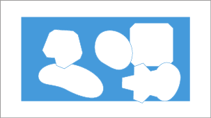
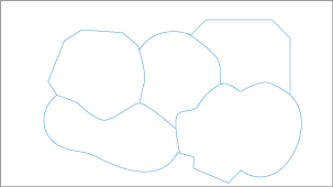
Mark Regions Tool
This tool enables you to copy a number of desired foreground structures (white) from the input image into an output image while the undesired structures are neglected. A marker image defines which structures are copied and which are neglected.
|
Parameter |
Description |
|---|---|
|
in1 |
The input image containing all structures |
|
in2 |
The marker image The marker image is black and contains white spots, the markers. Structures in the input image that overlap with one or more markers are neglected. All structures not overlapping with any marker are copied to the output image. |
|
Select Marked |
Activated: The effect is inverted. All marked structures are copied, all non-marked structures are neglected. |
NOT Tool
This tool performs a binary NOT operation on all pixels of the current image. All bits in the binary representation of each pixel's gray value are inverted.
|
Input Bit |
Output Bit |
|---|---|
|
0 |
1 |
|
1 |
0 |
This corresponds to subtracting the current value of each pixel from the maximum pixel value and yields the "negative image" of the current image, as known from photography.
The tool is not suitable for non-integer pixel types such as Float and Complex.
OR Tool
This tool performs a binary OR operation on the input images in1 and in2. For each pixel, the gray values are compared in their binary representation bit by bit.
The table shows how each bit of each pixel is compared.
|
Bit 1 |
Bit 2 |
Output Bit |
|---|---|---|
|
1 |
1 |
1 |
|
1 |
0 |
1 |
|
0 |
1 |
1 |
|
0 |
0 |
0 |
The tool can be used to combine binary masks or regions where the pixel type is binary and supports 0 (black) and 1 (white) only. If a pixel is white in at least one of the two input images, the output pixel is set to white. If a pixel is black in both input images, the output pixel is set to black.
Scrap Tool
This tool enables you to remove foreground structures (white) from the current image, depending on the size of the structures.
The size is defined as the number of pixels. Structures with a pixel size within a specified size interval are removed, structures with a pixel size outside the boundaries of the specified size interval are maintained.
|
Parameter |
Description |
|---|---|
|
Minimum Area |
The minimum number of pixels of the foreground structures to be removed |
|
Maximum Area |
The maximum number of pixels of the foreground structures to be removed |
|
Select in Range |
Activated: The effect is inverted. Structures with a size within the interval are maintained, structures with a size outside the interval boundaries are removed. |
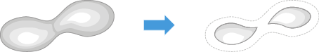
Separation Tool
This tool separates overlapping foreground structures automatically.
You can try this tool if separating the structures using segmentation does not yield the desired results.
|
Parameter |
Description |
|
|---|---|---|
|
Separation Mode |
Specifies how overlapping objects are treated |
|
|
– |
Morphology |
Pixels are "eroded" from the edge of the shape until it splits into two shapes. The result is two rounded objects, potentially with a large gap between them.
|
|
– |
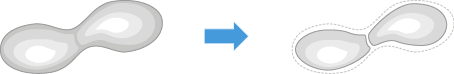
Watersheds |
The effect of this algorithm is best understood with an analogy: The shape is considered to contain two "valleys" with the two brightest pixels corresponding to the bottom of one valley each. If water were poured onto the shape, there would be a boundary ("watershed") that defines where water flows into one valley or the other. The shape is split along this boundary. The result is two shapes separated by a thin 1-pixel boundary. The rest of the shape perimeter remains unchanged.
|
|
Count |
Specifies how many times the chosen separation method is applied successively. |
|
Thinning Tool
This tool reduces the width of white lines on a black background until they are only a single pixel wide.
A common use of this tool is to tidy up output generated by an edge detector.
|
Parameter |
Description |
|---|---|
|
Thinning Element |
Specifies the mask element used to apply the iterative thinning operation. |
|
Count |
Specifies the number of times the tool is applied consecutively. The higher the Count, the higher number of pixels by which the width of lines is reduced. |
|
Prune |
Activated: Parasitic lines, which can result from edge detection and which do not contribute to the detected shapes, are reduced in length. The number of pixels by which the length of lines is reduced is specified by Count. |
|
Converge |
Activated: Independent of Count, the Thinning tool is applied consecutively until the image does not change anymore (i.e. the white lines are reduced to single pixel width). |
|
AxioVision Compatibility |
The algorithm was re-implemented in ZEN. The results differ from the results produced using AxioVision. Activated: A former version of the algorithm is used to get the same results as produced by AxioVision. |
Ultimate Erode Tool
This tool reduces the size foreground structures (white) in the input image. Thin connections between structures are removed and the structures are separated.
The tool is very similar to the Erode tool. In contrast to the basic Erode, this tool can erode structures repetitively until they would be deleted by the next erosion step.
If the tool operates on pixels on the border of the image, the structure element touches pixels outside the image. These invisible pixels are assumed to be white.
|
Parameter |
Description |
|---|---|
|
Structure Element |
Defines the shape of the neighborhood around each pixel taken into account while applying the erosion operation and thus to a certain degree the shape of the eroded structures. |
|
Count |
Enables you to increase the effective size of the structure element by controlling how many times the morphology operation is applied. The higher the Count value, the more the structures are eroded. The erosion for each structure stops if this structure would be removed in the next step. The entire process stops if all structures are eroded to the maximum, even if the Count value would demand further repetitions. |
|
Converge |
The tool is applied until all structures are eroded to the maximum and would be removed in the next step. |
See also
XOR Tool
This tool performs a binary XOR operation on the input images in1 and in2. For each pixel, the gray values are compared in their binary representation bit by bit.
The table shows how each bit of each pixel is compared.
|
Bit 1 |
Bit 2 |
Output Bit |
|---|---|---|
|
1 |
1 |
0 |
|
1 |
0 |
1 |
|
0 |
1 |
1 |
|
0 |
0 |
0 |
The tool can be used to combine binary masks or regions where the pixel type is binary and supports 0 (black) and 1 (white) only. If a pixel is white in one input image and black in the other input image, the output pixel is set to white. If a pixel is white in both input images or black in both input images, the output pixel is set to black.