Interactive Measurements
Interactive measurements enable you to measure the properties of a sample, for example, angles, area, and intensities of pixels. The tools can be classified as follows (the available tools depend on your hardware setup and licenses):
- Annotations
- Enable you to add text labels to an image, mark objects of interest, or determine the coordinates of a point in the standard or relative coordinate system.
- Areas/Contours
- The majority of these tools enable you to calculate the area (in pixels) enclosed by various shapes. Furthermore, the mean intensity of the enclosed pixels is also calculated. Some Area Tools are used to calculate the length of curves, such as the Spline Curve tool.
- Distances
- Enable you to measure angles and distances between lines, curves and points.
The software offers the possibility to use a magnetic cursor in your image. This cursor detects edges/contrast changes and automatically moves to them, which can help you to add measurements or annotations. Note that this cursor only works reliably on one channel, so for multi-channel images only activate one channel in the view options. The magnetic cursor can be activated and deactivated via the right-click context menu of your image, or with the shortcut Alt + C.
For more information on an individual tool, see the tool reference.
See also
Adjusting Interactive Measurements
You can adjust various properties of interactive measurements, for example:
- Line color, strength, and style
- Text font, color, and size
- Opacity
- Measurement results displayed in the in the Center Screen Area next to the interactive measurement and in the corresponding tool
- An interactive measurement workbench is selected.
- You have performed at least one interactive measurement.
- Select the desired interactive measurement tool.
- Click the gear wheel icon.

- Adjust the parameters as desired.
- The measurements are updated immediately.
Using Interactive Measurement Tools
Interactive measurement tools enable you to measure distances, angles, areas, and intensities of pixels. In the Favorites section you can arrange your favorite tools by simply dragging them from the tools selection to the favorites bar.
- An image is displayed.
- The Interactive Measurement workbench is selected.
- Select the desired measurement tool from the tool selection. Note that by default the Keep Measurement Tool checkbox at the bottom of the tool selection is activated. This will keep the selected tool active after you have drawn in a measurement.
- Alternatively, select a tool from the Favorites bar.
- If it is not visible, click + Add Tool and double-click on the desired tool.
Note that only parameters of the active tool are displayed in the workbench area. - Click to place the measurement tool in the image.
- For more information about how to use each tool, see Interactive Measurements Workbench.
- To add more measurements, repeat the above steps.
- The selected tool remains active until you press Esc or close the window Apply selected tool (Esc to abort).
If desired, you can modify the measurement as follows:
- Sorting interactive measurements
- Editing interactive measurements
- Adding an annotation to interactive measurements
- Repeating or correcting an interactive measurement
See also
Layering Interactive Measurements
Each measurement is stored in an imaginary layer. By default, the first measurement is the bottom layer and the most recent measurement is the top layer. You can change the order of the layers, for example if two measurements overlap and one is obscuring the other.
To move a measurement up or down a layer:
- Right-click the measurement.
- Select how you want to move the measurement:
- Bring Forwards: up one layer
- Send Backwards: down one layer
- Bring to Front: to top
- Send to Back: to bottom
See also
Adding an Annotation to Interactive Measurements
You can add an annotation to an interactive measurement, for example to label an area of the sample.
Adding an annotation
To add an annotation:
- At least one measurement is visible in the Center Screen Area.
- Double-click the measurement in the Center Screen Area.
- Enter the desired text.
- To add an extra line of text press the Enter key.
- Click outside the measurement.
You can change the formatting of the annotation in the same way as you change the appearance of the measurement result.
- You cannot apply different text formatting to the annotation and the measurement result.
- You cannot apply different formatting to individual words or characters of the annotation.
Removing an annotation
To remove an annotation:
- At least one measurement is visible in the Center Screen Area.
- Double-click the desired measurement.
- Delete all the text in the annotation.
- Click outside the measurement.
See also
Editing Interactive Measurements
You can change the following properties of an interactive measurement:
- Size and position of the entire measurement (measurement result and individual nodes)
- Position of measurement result
- Number and position of individual nodes
For some tools you can change their orientation (rotation or placement of the measurement arcs).
For more information, refer to the help topic for the corresponding tool.
Entire measurement
To change the properties of the entire measurement:
- At least one measurement is visible in the Center Screen Area.
- Click the desired measurement and perform one of the following actions:
|
Graphic |
Aim |
Action |
|---|---|---|
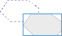
|
|
Move measurement |
Click within the bounding box and drag |
|
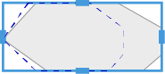
|
Resize freely |
Drag the sides of the bounding box |
|
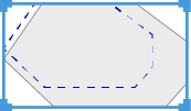
|
Resize (proportional) |
Press Ctrl and drag the corners of the bounding box |
Measurement result
To change the properties of the measurement result:
- At least one measurement is visible in the Center Screen Area.
- Click the desired measurement and perform the following action:
|
Graphic |
Aim |
Action |
|---|---|---|
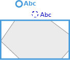
|
|
Move measurement result |
Drag the node of the measurement result |
Annotation position
To alter the position of an annotation:
- At least one measurement is visible in the Center Screen Area.
- Click the desired measurement.
- Place the cursor over the annotation node. The cursor changes to a hand icon.
- Drag the node to the new location.
Individual nodes
To change the properties of individual measurement nodes:
- At least one measurement is visible in the Center Screen Area.
- The measurement was created by defining multiple nodes.
- Right-click the desired measurement.
- Click Edit Points.
- Perform one of the following actions:
|
Graphic |
Aim |
Action |
|---|---|---|
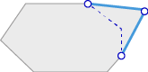
|
|
Move node |
Drag node |
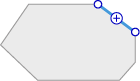
|
|
Add node |
Click between two nodes |
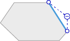
|
|
Remove node |
Press Ctrl and click node |
See also
Hiding an Interactive Measurement
Normally, when a job is run, interactive measurements are automatically placed on the image at the location specified in Create a new template and edit it within Job Mode. However, it is also possible to create an interactive measurement task where the image has no measurements pre-placed. In this case, ensure that the operator knows where to perform the measurement (e.g. using a suitable workbench description).
- Click the desired measurement.
- Delete the measurement using the DEL key on your keyboard.
The tool remains in the Workbench Area but the measurement is no longer displayed in the image. The operator running the job later can create the measurement freely instead of modifying a pre-placed measurement.
You can also use this feature to correct a faulty measurement while working in Create a new template and edit it within Job Mode:
- Delete the measurement from the image and click the Redraw button in the tool to repeat the measurement correctly.
See also
Changing Units of Measurements
- You have drawn in a measurement to an image, e.g. a Distance measurement.
- Select the measurement by clicking on it.
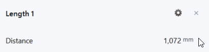
- Click on the Properties icon in the measurement box.
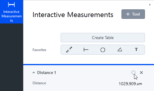
- The Properties dialog opens.
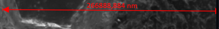
- Select the desired unit from the Unit drop-down list, e.g. mm instead of µm.
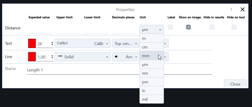
- The changed unit will be displayed in the image and in the measurement box.
Adding Measurements to a Live Image
- The 2D Acquisition or 2D Acquisition (automatic) Workbench is selected.
- You see the Live image of the microscope camera.
- Click on + Add Tool.
- The list of tools is displayed.
- Double-click on the desired measurement tool under Areas/Contours or Distances, e.g. Distance.
- The measurement tool is active.
- Draw in the measurement to the live image.
- If you click on Snap, the image will be acquired including the drawn in measurement. Do not forget to save the image to your file system.
Formatting Graphical Elements
Once you have applied annotations, angles or other graphical elements to your image, you can format each of them separately. It is only possible to format the elements in the Interactive Measurements workbench. If the formatted element is available in the Topography Measurements workbench, the applied format will be used there as well. The following tools of the workbenches correspond:
|
Topography Measurements workbench |
Interactive Measurements workbench |
|---|---|
|
Profile Distance tool |
Distance tool |
|
Profile Angel tool |
Angle tool |
|
Profile Line (x, y) tool |
Not available |
|
Profile Circle (Radius, In-Out) tool |
Circle (Radius, In-Out) tool |
- In the Interactive Measurement workbench, you have added text or measurements to an image, e.g. a distance measurement.
- Select the element, and from the context menu, select Format Graphical Elements.
- The following dialog is displayed.
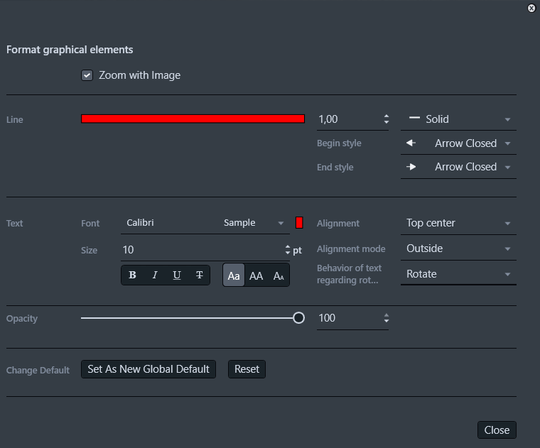
- Format the graphical elements according to your needs, e.g., click on the red line and choose a different color. Note that it is not possible to adapt the font size for a tool of the Topography Measurements workbench. To use the new formats for any measurement of this tool in both workbenches, click Set As New Global Default, and click Close.
- From now on, the format settings are used for all measurements of the configured tool, and for the corresponding tools of the Topography Measurements workbench.
ON THIS PAGE
- Interactive Measurements
- Adjusting Interactive Measurements
- Using Interactive Measurement Tools
- Layering Interactive Measurements
- Adding an Annotation to Interactive Measurements
- Editing Interactive Measurements
- Hiding an Interactive Measurement
- Changing Units of Measurements
- Adding Measurements to a Live Image
- Formatting Graphical Elements