Morphology Group
Morphology transformations enable you to analyze and modify structures and shapes in an image. Morphology transformations are non-linear and thus allow you to modify the image selectively while other portions of the image remain unchanged. Typical fields of application are quality assurance or medical image processing.
Morphology transformations are a type of neighborhood transformation: the image is analyzed pixel by pixel and each pixel is transformed depending on its neighbors. Thus the results of a morphology transformations depend on two factors:
- The type of morphology operation: the mathematical function used to evaluate each pixel and its neighbors
- The most common operations from which most others are derived are erosion (remove pixels from a bright structure) and dilution (add pixels to a bright structure).
- The structure element: the shape and size of the neighborhood taken into account for the analysis of each pixel
- The structure element reflects the structures in the image you wish to analyze. For example, to find vertical structures use the Vertical structure element.
You can imagine the structure element as a stencil which is moved over the image pixel by pixel. Only the pixels within in the stencil area are visible and taken into account for the morphology transformation. The applied operation (e.g. erosion or delusion) then determines if and how the central pixel within the stencil area is changed.
In the software you first the specify the morphology operation by selecting the corresponding tool. From the tool you then select the structure element and its size (defined by the number of repetitions the structure element is applied).
See also
Structure Elements
The shape of the structure element makes the morphology transformation sensitive to specific shapes in the input image.
|
Type |
Appearance |
|---|---|
|
Horizontal |
|
|
Diagonal 45° |
|
|
Vertical |
|
|
Diagonal 135° |
|
|
Cross |
|
|
Square |
|
|
Octagon |
|


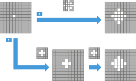
The size of the structure elements is fixed to five times five pixels. You can increase the effective size by applying a structure element multiple times. This is equal to applying an equivalent larger structure element once.
|
1 |
Dilation applied once with a larger structure element. |
|
2 |
Dilation applied twice with a smaller structure element yielding the same result. This method is used in the morphology tools. |
See also
Close Tool
This tool connects bright structures on a darker background in the input image while the size of the structures is preserved as far as possible.
The Close tool applies Dilate to expand the structures and connect them and then Erode to restore their size.
|
Parameter |
Description |
|---|---|
|
Structure Element |
Defines the shape of the neighborhood around each pixel taken into account while applying the morphology operation. |
|
Count |
Enables you to increase the effective size of the structure element by controlling how often the morphology operation is applied. |
|
Binary |
|
See also
Dilate Tool
This tool expands bright structures on a darker background in the input image by adding pixels to the boundaries of these structures. Small gaps between structures are filled and these structures are connected.
If the structure element touches at least one bright pixel, the pixel currently operated on is turned into a bright pixel.
|
Parameter |
Description |
|---|---|
|
Structure Element |
Defines the shape of the neighborhood around each pixel taken into account while applying the morphology operation. |
|
Count |
Enables you to increase the effective size of the structure element by controlling how often the morphology operation is applied. |
|
Binary |
|
See also
Erode Tool
This tool reduces the size of bright structures on a darker background in the input image. Thin connections between structures and smaller structures disappear.
If the structure element touches at least one dark pixel, the pixel currently operated on is turned into a dark pixel.
|
Parameter |
Description |
|---|---|
|
Structure Element |
Defines the shape of the neighborhood around each pixel taken into account while applying the morphology operation. |
|
Count |
Enables you to increase the effective size of the structure element by controlling how often the morphology operation is applied. |
|
Binary |
|
See also
Gradient Tool
This tool emphasizes image areas of varying gray values (intensity). The results are similar to those of an edge detector.
A dilated and an eroded version of the input image is created using the same structure element. Then the two images are subtracted from each other. As a result, each pixel is replaced by the difference between the maximum and minimum gray value in its neighborhood. The difference is zero for regions of constant gray values and increases for larger changes in gray values (i.e. edges).
|
Parameter |
Description |
|---|---|
|
Structure Element |
Defines the shape of the neighborhood around each pixel taken into account while applying the morphology operation. |
|
Count |
Enables you to increase the effective size of the structure element by controlling how often the morphology operation is applied. |
See also
Gray Reconstruction Tool
This tool expands (i.e. dilates) bright structures on a darker background in one input image (marker) repetitively until the structures fill shapes provided by another input image (mask). The bright structures cannot expand beyond the areas defined by the mask shapes and the process stops automatically when the shapes are completely filled.
For example, you can use gray reconstruction to extract marked structures, to filter out structures touching the image border, or to detect or fill holes within a structure. You can find an example of use in Morphology Examples.
|
Parameter |
Description |
|---|---|
|
in1 (Marker) |
The image to be reconstructed by dilation |
|
in2 (Mask) |
The image providing the shapes which constrain the dilation of the first image |
|
Structure Element |
Defines the shape and size of the neighborhood around each pixel taken into account while applying the dilations This has an effect on how the structures originating from the "seed pixels" in the marker image are reconstructed. If you are unsure which one to use, try generic uniform structure elements like Square or Octagon first. |
See also
Open Tool
This tool separates bright structures on a darker background in the input image while the size of the structures is preserved as far as possible. Thin connections between structures and smaller structures disappear.
The Open tool applies Erode to remove the undesired pixels and then Dilate to restore the size of the desired structures.
|
Parameter |
Description |
|---|---|
|
Structure Element |
Defines the shape of the neighborhood around each pixel taken into account while applying the morphology operation. |
|
Count |
Enables you to increase the effective size of the structure element by controlling how often the morphology operation is applied. |
|
Binary |
|
See also
Top Hat Black Tool
This tool retains the dark structures of the image that are smaller than the structuring element. You can use this tool to correct uneven illumination when the background is bright.
The black top-hat is defined as the morphological closing of an image minus the image itself.
|
Parameter |
Description |
|---|---|
|
Structure Element |
Defines the shape of the neighborhood around each pixel taken into account while applying the morphology operation. |
|
Count |
Enables you to increase the effective size of the structure element by controlling how often the morphology operation is applied. |
See also
Top Hat White Tool
This tool retains the bright structures of the images that are smaller than the structuring element. You can use this tool to correct uneven illumination when the background is dark.
The white top-hat of an image is defined as the image minus its morphological opening.
|
Parameter |
Description |
|---|---|
|
Structure Element |
Defines the shape of the neighborhood around each pixel taken into account while applying the morphology operation. |
|
Count |
Enables you to increase the effective size of the structure element by controlling how often the morphology operation is applied. |
See also
Watersheds Tool
This tool enables you to segment (i.e. to separate) touching structures within an image.
The image is interpreted as a topographic map in which gray values represent elevation. Bright pixels are interpreted as mountains and dark pixels as valleys. The tool virtually floods the valleys and finds the barriers encircling each valley. These barriers are the watersheds used for segmentation of the image.
A valley is defined as a local gray value minimum from which the gray value increases in any direction and is limited by local maxima. As a result, the degree of segmentation is often higher than expected by the visual impression of the image. To improve results you can increase the contrast by applying the Top Hat White and Top Hat Black tools in combination.
|
Parameter |
Description |
|---|---|
|
Basins |
|
See also
Morphology Examples
Most morphology transformations are based on erosion and/or dilation. The examples below show how a bright structure on a dark background can be expanded using dilation or made smaller using erosion. The structure element determines how the structure is modified and thus how the final result looks like. In the example the structure element Cross is used:

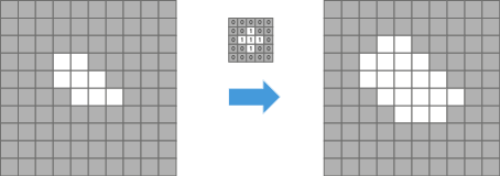
Erosion
Erosion removes pixels from bright structures. The structure element scans the input image pixel by pixel. Each pixel is set to the minimum value of all neighboring pixels currently covered by the structure element.
The example below shows erosion applied to a binary image (i.e. only black or white and no gray scale). In this case, a pixel is set to black if at least one of the neighboring pixels covered by the structure element is black. If all neighboring pixels covered by the structure element are white, the central pixel remains white.
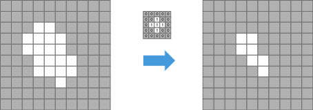
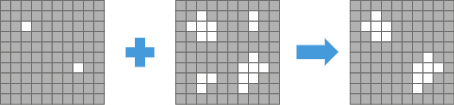
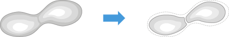
Dilation
Dilation adds pixels to bright structures. The structure element scans the input image pixel by pixel. Each pixel is set to the maximum value of all neighboring pixels currently covered by the structure element.
The example below shows dilation applied to a binary image (i.e. only black or white and no gray scale). In this case, a pixel is set to white if at least one of the neighboring pixels covered by the structure element is white. If all neighboring pixels covered by the structure element are black, the central pixel remains black.
Gray Reconstruction
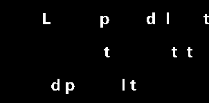
Gray reconstruction can be used to extract elements with a characteristic feature. The example below shows how in two steps letters with long vertical features can be extracted from a text.
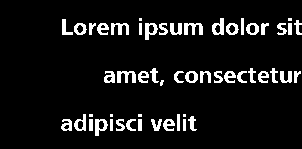
In the first step the image is eroded using the Erode tool so that only bright pixels of vertical structures are left, i.e. pixels of the vertical elements of letters such as L, p, or d. Vertical is used as the Structure Element.
In order to remove a sufficient number of bright pixels to isolate the lengthy elements but not to remove too many pixels, the effective size of the structure element is adjusted. A Count of six yields the image below:
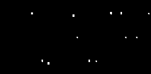
In the second step all letters containing long vertical elements are reconstructed using the Gray Reconstruction tool. The image above is used as the marker (in1) and the original image is used as the mask (in2). To reconstruct the letters uniformly in both directions, the structure elements Square or Octagon are suited.
The gray reconstruction results in the image below: