Tiles & Positions
This module enables you to acquire images that are made up of a number of individual images (tiles). To do this, it is possible to define tile regions and positions.
Acquiring a Tile Image
The tiles acquisition workbenches enable you to acquire an image of a large sample area. You define the area to be acquired and the system then acquires the corresponding tiles (images of neighboring sample areas) automatically and assemble them to a large image.
- The Tiles (manual) or Tiles (interactive) workbench is selected.
- The sample is sufficiently illuminated and in focus.
- The microscope is equipped with a motorized stage.
- Set up the camera using the Camera tool.
- Select the objective in the Magnification tool.
- Define and create the region of which you wish to acquire the tile image using the Tiles Setup (manual) or Tiles Setup (interactive) tool.
- The Center Screen Area displays the area you wish to acquire and a preview of the tiles to be acquired, including overlap.
- Set up the stitching method to be applied after acquisition using the Tile Stitching tool.
- Add the Focus Correction tool to apply a supporting method for focusing such as Software Autofocus or Focus Support Points / Focus Surface.
- In the Workbench Area, click the Start button.
The software acquires the tiles and stitches (merging the individual images together) the tile image automatically.
See also
Acquiring a Tile Image with Extended Depth of Focus
The Tiles with EDF (interactive) workbench enables you to combine a tile image with extended depth of focus (EDF) acquisition. A Z-stack image is acquired for each tile.
- The Tiles with EDF (interactive) workbench is selected.
- The sample is sufficiently illuminated and in focus.
- The microscope is equipped with a motorized stage.
- Set up the camera using the Camera tool.
- Select the desired objective in the Magnification tool.
- Define the region of which you wish to acquire the tile image using the Tiles Setup (interactive) tool.
- Set up the focus range and number of slices to be acquired for each tile in the Motorized Extended Depth of Focus tool.
- Set up the stitching method to be applied after acquisition of using the Tile Stitching tool.
- In the Workbench Area, click the Start button.
The software acquires the tiles with extended depth of focus and assembles the tile image automatically.
Each tile is acquired multiple times at different focus positions. Thus, combining tile acquisition with extended depth of focus increases the acquisition time considerably.
Using Focus Support Points for Tile Images
- You have selected a tiles workbench, e.g. Tiles (interactive).
- You have set up a tiles acquisition (e.g. 3x3 tiles).
- Click + Tool to add a tool.
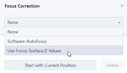
- Double-click the Focus Correction tool.
- The tool will be added to the workbench.
- In the Focus Correction tool, select Focus Surface.
- Click Distribute Default Points.
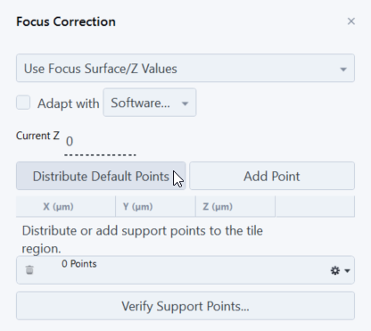
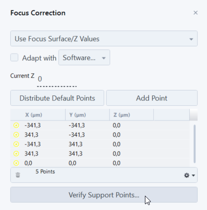
- 5 support points are added to the tiles acquisition.
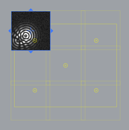
- Click Verify Support Points to check each point, if the focus is set correctly.
- The Verify Support Point dialog will open and the stage moves to the first support point.
- Check if the image is in focus. If not, refocus the image. We recommend to use the Software Autofocus to help you find the correct focus setting. If the Software auto focus does not work fine, you can set the focus manually.
- Click Set Z & Move to Next if the focus is set correctly for the current support point.
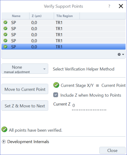
- The stage will move to the next support point. Repeat the verifying process until all support points are verified.
- The message All points have been verified appears in the dialog. Click Close to exit the dialog and start the tiles acquisition.
Preview Images Tool
Using this tool you can select an acquired or loaded image as a preview image for a tiles acquisition. Therefore you can create an image with a lower magnification and load it as preview image. The preview image can be then used for navigating to a specific area which you want to observe in detail. You now can switch to a higher magnification and acquire another tile image.
See also
Tiles Options Tool
This tool enables you to add advanced options when acquiring tiles.
|
Parameter |
Description |
|
|---|---|---|
|
Move Focus to Load Position Between Regions/Positions |
Activated: To prevent possible damage, the focus drive is moved to the load position while moving to another tile region or position. This option is only available in the following workbenches:
|
|
|
Tile overlap |
Defines the overlap of the re-tiled tiles in %. This option is only available in the following workbenches:
|
|
|
Travel in Tile Regions |
Defines the stage travel behavior. |
|
|
– |
Meander |
Default value. Acquires tile regions following a meander pattern alternately from both travel directions: from left to right and then from right to left. This scan movement is fastest. |
|
– |
Comb |
Acquires tile regions following a comb pattern always from one travel direction only: from left to right. This scan movement is most precise. |
|
– |
Spiral |
Acquires tile regions following a spiral pattern from the center of the region to the outer bounds in a clockwise motion. This scan movement works only for regions with rectangular or elliptical contours. |
|
Tile Regions/Positions |
Activated: Adapts the stage movement automatically to the location of the individual tile regions and positions. If you add or remove tile regions or positions, the sequence of acquisition therefore also changes. |
|
|
– |
Sort by Y, then X |
Sorts tile regions and positions by their absolute position: first X, then Y. |
|
– |
Sort by X, then Y |
Sorts tile regions and positions by their absolute position: first Y, then X. |
See also
Tiles Setup (interactive) Tool
With this tool you can interactively setup a tile region simply by moving the stage. You just have to set the start and end position of the desired tile region and the tile region is generated automatically.
If the sample height varies by a large amount, we recommend to add a focus correction method. Therefore you first have to add the Focus Correction tool. There you can select a focus correction method (e.g. Software Autofocus or Focus Surface) which is applied during the acquisition of the tile image.
|
Parameter |
Description |
|---|---|
|
Start with Current Position |
Adds the current x/y/z position as the starting point for the new tile region. The button then changes to Extend to Current Position. Move the stage to the desired end position and click on the button to setup the tile region. If you click on Start on top of the workbench, the final tile image will be acquired. |
|
Delete |
Deletes the created tile region. |
Tiles Setup (free drawing) Tool
With this tool you can setup tile regions by drawing different contours (rectangle, ellipse, polygon) to create tile regions. The tile region is generated automatically according to the size of your drawing. When you click Start on top of the workbench, the final tile image is acquired.
Note: The Tiles (free drawing) workbench and the Tiles Setup (free drawing) tool are only visible in existing jobs where they were added in previous versions of ZEN core. They are not available any more for Free Mode or for new jobs.
If the sample height varies by a large amount, we recommend to add a focus correction method. For this, add the Focus Correction tool and select a focus correction method. This is applied during the acquisition of the tile image.
Tiles Setup (manual) Tool
With this tool you can manually setup a tile region wether by entering the number of tiles (e.g. 3 x 3) or size of the tile region (e.g. 4000µm x 4000µm). The individual images (single tiles) are acquired and then stitched together to create the final tile image.
If the sample height varies by a large amount, we recommend to add a focus correction method. For this, add the Focus Correction tool and select a focus correction method. This is applied during the acquisition of the tile image.
|
Parameter |
Description |
|---|---|
|
Create tile region |
Creates a preview of the tile region which you have setup. The tile region is created at the current stage position. The yellow grid shows the tiles to be acquired, including an overlap. The frame shows the total (sample) area of interest. If you click on Start on top of the workbench, the final tile image will be acquired. |
|
Tiles |
If selected, you can enter the number of tiles to be acquired, e.g. 3x3 tiles. The size of the tile region is calculated automatically. |
|
Size |
If selected, you can enter the size of the tile region to be acquired in µm, e.g. 4000 x 40000 µm. The number of tiles is calculated automatically. |
Tiles Setup (measurement area) Tool
|
Parameter |
Description |
|
|---|---|---|
|
Contour |
Switches the option to select rectangular or circular contour shape. |
|
|
Field Size |
Only visible with rectangular contour shape.
If you change the field size, the area is changed in relation. |
|
|
Fields |
Only visible with rectangular contour shape. If you change the amount of standard measuring fields, the measurement area is changed accordingly. |
|
|
Circle Diameter |
Only visible with circular contour shape. |
|
|
Area |
Specifies the acquired measurement area in mm2. If you change the measurement area, the amount of fields is changed accordingly. |
|
|
Add Tile Region |
Adds a new tile region with the specified size values. The region is added with the top left position at the current stage position. The contour geometry of the tile region is automatically adjusted to fit an integer multiple ot the current field size. Therefore, the area might be a bit larger than expected. The region is created in a way that an integer multiple of the current field size fits into the contour geometry (in columns and rows). Example: If you enter a field count of 6, a tile region with 3 x 2 fields is created (3 columns, 2 rows). This has also the consequence that for certain field counts (all prime numbers), a region with exactly that field cannot be created. For example, if you enter a field count of 11, a tile region with 4 x 3 (= 12) fields is created. This in general means that, if you do not change the created tile regions manually, the regions are always integer multiple of the field size. |
|
|
Tile Region Table |
This table provides an overview of all added tile regions. The checkbox in front of each entry activates the respective tile region. The following parameters are available in the table: |
|
|
Name |
Displays the name of the tile region. A click on the name allows you to edit it. |
|
|
Tiles |
Displays the number of tiles of the region. |
|
|
Z (µm) |
Displays and sets the z position of the region. |
|
|
Area |
Displays the area of the region in mm2. |
|
|
Size |
Displays the size of the region. |
|
|
|
Moves up the entry one position in the list. |
|
|
|
Moves down the entry one position in the list. |
|
|
|
Deletes the currently selected region. |
|
|
|
||
|
– |
Set Current Z for Selected Tile Regions |
Sets the current z-position for all selected tile regions. |
|
– |
Set Current X/Y/Z for Selected Tile Region |
Sets the current x/y/z-position for all selected tile regions. |
|
– |
Delete |
Deletes the currently selected tile region. |
|
– |
Delete All |
Deletes all tile regions. |
|
– |
Activate |
Activates the current tile region for acquisition. |
|
– |
Deactivate |
Deactivates the current tile region for acquisition. |
|
– |
Sort |
Enables you to sort the entries in the tables. |
|
– |
Import Tile Regions |
Opens a file browser to import a list of already defined tile regions. |
|
– |
Export Tile Regions |
Opens a file browser to export the list of your currently defined tile regions as a file. |


|
Parameter |
Description |
|
|---|---|---|
|
Lock Contour of all Regions |
Specifies whether and how the contour geometry of all tile regions is locked. |
|
|
– |
None |
The contour of all tile regions is not locked. |
|
– |
Area |
The contour area of all tile regions remains constant. |
|
– |
Size |
The contour size and area of all tile regions cannot be changed. |
|
Adjust to Integer Multiple of Field Size |
Adjust the contour geometry of all tile regions to fit an integer multiple of the current field size. After that, the area might be slightly larger. If the size of the tile regions is not locked, you can modify the size of the tile regions manually by using the mouse handles in the graphical representation. |
|
Tiles Setup (multiple regions) Tool
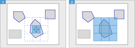
With this tool you can setup multiple tile regions by drawing different contours (rectangle, ellipse, polygon). The tile regions are generated automatically according to the size of your drawings.
If the sample height varies by a large amount, we recommend to add a focus correction method. For this, add the Focus Correction tool and select a focus correction method. This is applied during the acquisition of the tile image.
|
Parameter |
Description |
|
|---|---|---|
|
Contour |
Selects which contour you want to use for drawing the tile region. |
|
|
– |
|
Enables you to select an already created tile region to move or resize it. |
|
– |
|
Enables you to draw a rectangular tile region. |
|
– |
|
Enables you to draw an elliptical tile region. |
|
– |
|
Enables you to draw a polygonal tile region. |
|
Tile Region Table |
This table provides an overview of all added tile regions. The checkbox in front of each entry activates the respective tile region. The following parameters are available in the table: |
|
|
Name |
Displays the name of the tile region. A click on the name allows you to edit it. |
|
|
Tiles |
Displays the number of tiles of the region. |
|
|
Z (µm) |
Displays and sets the z position of the region. |
|
|
Area |
Displays the area of the region in mm2. |
|
|
Size |
Displays the size of the region. |
|
|
|
Moves up the entry one position in the list. |
|
|
|
Moves down the entry one position in the list. |
|
|
|
Deletes the currently selected region. |
|
|
|
||
|
– |
Set Current Z for Selected Tile Regions |
Sets the current z-position for all selected tile regions. |
|
– |
Set Current X/Y/Z for Selected Tile Region |
Sets the current x/y/z-position for all selected tile regions. |
|
– |
Delete |
Deletes the currently selected tile region. |
|
– |
Delete All |
Deletes all tile regions. |
|
– |
Activate |
Activates the current tile region for acquisition. |
|
– |
Deactivate |
Deactivates the current tile region for acquisition. |
|
– |
Sort |
Enables you to sort the entries in the tables. |
|
– |
Import Tile Regions |
Opens a file browser to import a list of already defined tile regions. |
|
– |
Export Tile Regions |
Opens a file browser to export the list of your currently defined tile regions as a file. |


See also
Tiles Stitching Tool
This tool enables you to combine a set of tiles into one large image.
This tool takes a tile image with the individual tiles placed next to each other as input and returns a single large image. The tiles are shifted and rotated against each other to make the transitions between them as seamless as possible. In addition, the tool enables you to correct uneven exposure (shading), either automatically or by means of a reference image.
|
Parameter |
Description |
|
|---|---|---|
|
Perform Stitching |
Activated: Stitching is performed after acquisition of the individual tiles |
|
|
Edge Detector |
When acquiring tiles to create a single large image, the stage movement is not precise down to the pixel level of the camera sensor. To bypass this technical limitation and to have a margin to compensate for this inaccuracy, tiles are usually overlapped by a few percent. To align the tiles, the overlaps between neighboring tiles are analyzed. An edge detector may improve analysis results. |
|
|
– |
Yes |
Applies and edge detection algorithm to the tiles internally to improve analysis of the overlaps between neighboring tiles. This may improve the alignment of the tiles and thus the stitching result. |
|
– |
No |
Omits edge detection. The quality of alignment of the tiles may be reduced. |
|
Minimal Overlap |
The amount of overlap between neighboring tiles (in % of the area of a single tile) expected by the stitching tool. The tool evaluates this amount of overlap or more as required. The value to the overlap that was used for acquisition of the tiles is set. Larger values may improve the result but increase calculation time. |
|
|
Max Shift |
Specifies the maximal extent of shift (in % of the area of a single tile) which can be applied to a tile during stitching. |
|
|
Comparer |
Specifies how the conformance of the tiles in the overlapping regions is evaluated. |
|
|
– |
Basic |
Basic comparison (faster) |
|
– |
Best |
Complex comparison (slower) |
|
– |
Optimized |
Optimized comparison |
|
Global Optimizer |
Specifies the number of overlaps evaluated during stitching. Evaluating more overlaps per tile yields a better stitched image, but requires more calculation time. |
|
|
– |
Basic |
Only one overlap per tile is evaluated. |
|
– |
Best |
All overlaps of a tile are evaluated. |
|
Defaults |
Resets all tool settings to the default values. |
|
|
Reset |
Enables you to return the output image back to its original form (input) after applying the stitching. |
|
|
Redo |
Enables you to return to the output form by reapplying the desired stitch settings. |
|
See also
Tiles (free drawing) Workbench
This workbench enables you to create tile images on a motorized stage by setting up the tile region with freehand drawing tools.
Note: The Tiles (free drawing) workbench and the Tiles Setup (free drawing) tool are only visible in existing jobs where they were added in previous versions of ZEN core. They are not available any more for Free Mode or for new jobs.
See also
Tiles (interactive) Workbench
This workbench enables you to acquire an image of a large sample area composed of tiles: a tile corresponds to the area the camera is able to acquire with a single acquisition.
You can specify multiple areas of interest on your sample. The software defines the total area which needs to be acquired and thus the required number of tiles. The tiles are then acquired automatically (the stage movement is controlled by the software) and merged into a single image.
See also
Tiles (manual) Workbench
This workbench enables you to acquire an image of a large sample area composed of tiles: a tile corresponds to the area the camera is able to acquire with a single acquisition.
You specify the area of interest on your sample you wish to acquire by defining a corresponding region in the software. You can define the region by the number of tiles to be acquired or by the size in micrometers. The tiles are then acquired automatically (the stage movement is controlled by the software) and merged into a single image.
See also
Tiles (measurement area) Workbench
This workbench enables you to acquire one or more tile images using a motorized scanning stage by adding multiple tile regions with a defined measurement area. A number of specimens can be configured for automated tiles image acquistion. It is optimized for standard based NMI Analysis.
In case of multi-specimen-setup, you can define individual values for each sample.
See also
Tiles (multiple regions) Workbench
This workbench enables you to create tile images on a motorized stage by setting up the tile region with freehand drawing tools. With this workbench you can draw multiple tile region, which are then acquired in a single acquisition.
See also
Tiles with EDF Workbench
This workbench enables you to acquire an image of a large sample area by specifying multiple tile regions on your sample which you wish to combine into a large image. For each tile region, a z-stack of images is acquired and merged afterwards into an extended depth of focus (EDF) image.
The stage movement and acquisition of the individual tiles is controlled automatically.
See also
Height Stitching and Blending Tool
This tool takes a tile image with the individual tiles placed next to each other as input and returns a single large image. For the best result and if necessary the th x, y and z position of the individual tiles is adjusted.
|
Parameter |
Description |
|---|---|
|
Acceptable difference |
Defines the distance value between each tile. |
|
Lower Threshold |
Defines the minimum value to which the lowest occurring pixel value is mapped. |
|
Upper Threshold |
Defines the maximum value to which the highest occurring pixel value is mapped. |
|
Execute Blending |
Activated: The residual artifacts on the edges of the tiles are reduced. |
See also
ON THIS PAGE
- Tiles & Positions
- Acquiring a Tile Image
- Acquiring a Tile Image with Extended Depth of Focus
- Using Focus Support Points for Tile Images
- Preview Images Tool
- Tiles Options Tool
- Tiles Setup (interactive) Tool
- Tiles Setup (free drawing) Tool
- Tiles Setup (manual) Tool
- Tiles Setup (measurement area) Tool
- Tiles Setup (multiple regions) Tool
- Tiles Stitching Tool
- Tiles (free drawing) Workbench
- Tiles (interactive) Workbench
- Tiles (manual) Workbench
- Tiles (measurement area) Workbench
- Tiles (multiple regions) Workbench
- Tiles with EDF Workbench
- Height Stitching and Blending Tool