Multi-Channel Acquisition
This module enables you to acquire multi-channel images. The Smart Setup functionality delivers proposals for combinations of dyes or contrast methods based on the available hardware.
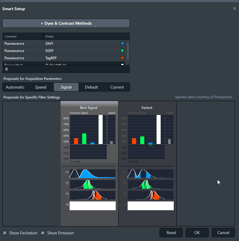
Smart Setup
In Smart Setup you configure channels. Select the fluorescent dyes and/or contrast methods that you want to include from a large dye database. Smart Setup takes the configuration of your microscope hardware and the properties of the selected dyes into account. Based on this information, it makes one or more suggestions for acquisition.
Note that Smart Setup tries to configure the components of your system for the acquisition of multi-channel images.
To open Smart Setup, select Free Mode > 2D Multi-Channel Acquisition workbench > Channels tool > Open Smart Setup. You can also open it in Job Mode.
See also
Configuring Multi-Channel Acquisition with Smart Setup
If Smart Setup is unable to make a proposal, it is not possible to use the selected combination of dyes and contrast methods with the current microscope hardware to make acquisitions.
Select other dyes or another contrast method.
- Select Free Mode > 2D Multi-Channel Acquisition workbench > Channels tool > Open Smart Setup.
- The Smart Setup dialog opens.
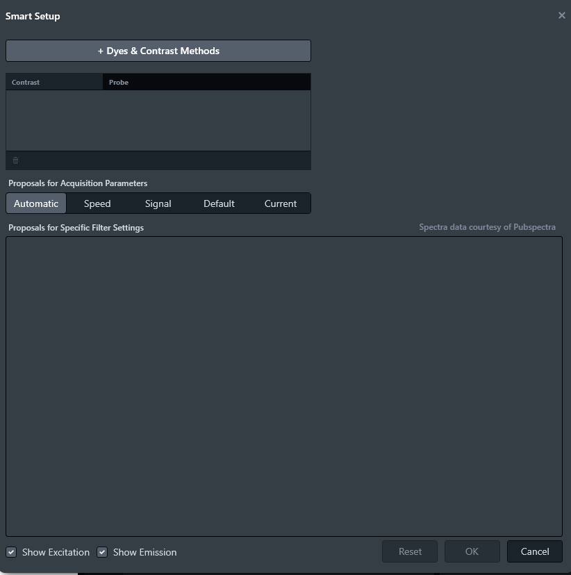
Smart Setup does not contain any dyes, contrast methods, or proposals. - To add a dye or contrast method, click + Dyes & Contrast Methods.
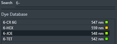
- The Add Dye or Contrast Method dialog opens.
- From the Dye Database list, select a fluorescent dye. Use the Search field to find the desired dye quickly, and double-click to add the selected dye.
- From the Contrast Methods list, select the corresponding contrast method, double-click to add the selected contrast method.
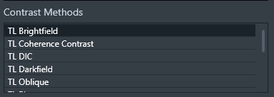
Note that you can only add channel combinations where a suitable proposal can be made based on the available hardware. - Close the dialog when you have selected the desired channels.
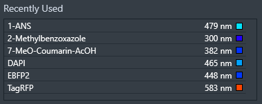
- The selected dyes will be listed in the Recently Used list for your next multi-channel acquisition configuration.
- The proposal is displayed in the Smart Setup dialog.
- From the Proposals for Acquisition Parameters, select the desired parameter, see Buttons to Optimize Acquisition Parameters.
- Click OK.
- You have configured multi-channel acquisition with Smart Setup. Proceed in the 2D Multi-Channel Acquisition workbench to acquire multi-channel images. In the Channels tool, a list with the selected dyes is displayed.
See also
Operator Workflow - Counting Cells
Operator workflows are designed by Supervisors. In the following you see the operator workflow Counting Cells Live, which allows to count fluorescently-labeled nuclei that can serve as a proxy for the cell number.
|
Tasks |
Description |
To Do |
|---|---|---|
|
Form |
The input form ZEISS Cells is provided. The form is displayed in the report. |
The default form is displayed. To change the form, in the Form Selection tool, select the form, see Form Selection Tool. Fill in relevant data according to your sample. |
|
2D Multi-Channel Acquisition |
Acquire images. |
To acquire multi-channel images, open Smart Setup and add dyes and contrast methods according to your sample. The first channel should be the fluorescently-labeled nuclei. Smart Setup provides proposals setting the light source, camera and filter setting, see Configuring Multi-Channel Acquisition with Smart Setup. Adjust the acquisition parameters, e.g. measure the exposure time, and then take a snap. |
|
Image Segmentation |
Generate one mask for all nuclei per cell. |
Generate masks for nuclei, which are then counted, see Automatic Segmentation. To separate neighboring nuclei use a separation tool, e.g. Watersheds. If a large part of the image is selected initially, use background subtraction. |
|
Region Filter |
Results are refined based on area and circularity of the objects. |
To refine the selection to limit the analysis to one object or nucleus per cell, use region filters for area and circularity, see Region Filter. |
|
Measurement Data |
Check the results based on the previously conducted image analysis. The results are displayed in a table. |
To select an object, click a value in the table, and to check the size of a certain object, click the object in the Center Screen Area. For more information, see Measurement Data Tool. |
|
Report |
Creates a report document, see Reports. You can print the report. The report contains the following information:
|
For your documentation, you create a report. |
2D Multi-Channel Acquisition Workbench
This workbench enables you to acquire 2D multi-channel images.
See also
Channels Tool
With this tool you configure multi-channel acquisition.
The Channels tool is available in ZEN starter as well.
No coded or motorized components are supported here. However, you can adjust the camera.
Once you have selected the channels, it makes one or more suggestions for acquisition. You can adopt these as required and make further changes to them.
To use longer exposure times than 10 seconds when acquiring images, for some cameras, e.g. Axiocam 7xx series, you have to define and turn on a black reference for long exposure times under 2D Acquisition workbench > Extended Camera tool > Post Processing Section, see Post Processing Section. Black reference defined in the 2D Acquisition workbench is also applied in the 2D Multi-Channel Acquisition workbench.
|
Parameter |
Description |
|
|---|---|---|
|
Open Smart Setup |
Opens the Smart Setup dialog, see Smart Setup. |
|
|
Measure Exposure |
Starts an exposure time measurement for all currently active channels. |
|
|
List of channels |
Displays a list of channels you have selected from the Add Dye or Contrasting Method dialog, see Configuring Multi-Channel Acquisition with Smart Setup. If you change the selection of a channel, the live image is switched accordingly. If you modify light source or channel-specific camera settings, e.g. exposure time, the modification is immediately updated in the live acquisition. |
|
|
|
Moves the selected channels up or down. |
|
|
|
Deletes the selected channels. |
|
|
Ref. |
Sets the selected channel as reference channel for focus actions or stitching during acquisition. |
|
|
Lightsource |
Displays a list with light source settings depending on the used light source. Adjusting the parameters of the light sources is possible without saving it to the hardware settings. |
|
|
– |
HXP 120/200 V |
Adjusts the intensity in discrete steps with the arrow keys or the slider.
|
|
– |
TL Lamp |
For Brightfield channel. LEDs refer to %.
|
|
– |
Colibri 7/5/3 |
Up to 7 LEDs are displayed depending on the hardware. The number of available LEDs depends on the used Colibri version. The following Colbri 7 versions with the corresponding LEDs are available:
The Colbri 5 version RGB-UV is with the corresponding 385, 475, 555, 630 LEDs available. It is possible to activate all LEDs simultaneously which means that either 555 or 590 nm can be turned on, if both are available.
The following Colibri 3 versions with the corresponding LEDs are available:
|
|
Deactivate all LEDs/Reactivate LEDs |
Only visible with Colibri 7/5 lightsource. De- or reactivates all active LEDs to the status when the deactivate button was last used. |
|
|
Exposure |
||
|
– |
Auto Exposure |
The exposure time is calculated automatically every time an image is acquired. For color cameras of the Axiocam series in b/w mode, the exposure time is determined in the b/w mode. This might lead to overexposure of individual pixels. The histogram displays the b/w mode and therefore does not reflect overexposure of individual pixels, which can be detected in the RGB mode with the same exposure time. |
|
– |
Set Exposure |
Starts a one time measurement of the exposure time, which is then used for all subsequent images. Deactivates the Auto Exposure checkbox. For color cameras of the Axiocam series in b/w mode, the exposure time is determined in the RGB mode to avoid unintended overexposure of pixels. Depending on the light source, this might lead to less usage of the histogram, i.e. dimmer images, than specified by the intensity value. To compensate for under- or overexposure, the intensity value can be adjusted. |
|
– |
Time |
Adjusts the exposure time for the camera. Use the slider or spin box. Select the unit of time from the drop down list:
|
|
– |
Intensity |
Defines the range of the histogram that is used for exposure determination and therefore compensates for underexposure or overexposure.
Use the slider or spin box to adjust the value. |
|
Shading |
||
|
– |
Correction |
Uses the calculated shading correction for this channel. |
|
– |
Define |
Automatically calculates the shading correction, see Applying the Shading Correction. |
|
– |
Global |
Performs an objective-specific shading correction. |
|
– |
Specific |
Default method. Performs channel-specific shading correction. The fluorescence filter block used is saved with the shading file. If the fluorescence channel is changed, a previously created reference image is also loaded. |
|
EM Gain |
Only visible for EMCCD camera models. Sets the EM gain value. |
|


See also
Camera - Global Settings Tool
With this tool you configure the color mode for the selected camera. The tool is only available for color cameras.
|
Parameter |
Description |
|
|---|---|---|
|
Color Mode |
Switches to the desired color mode. |
|
|
– |
RGB |
Based on the RGB (Red-Green-Blue) color model. Transmits the image data of a color camera unchanged. This corresponds to the standard operating mode of a color camera. |
|
– |
B/W |
Treats the image data of the color channels as grayscale. The data of related color channels are averaged. The saturation of the camera appears reduced as a result. This process does not change the spectral properties of a color camera. The image information of the color sensor still undergoes color interpolation. An infrared filter also restricts the spectral sensitivity of the color camera compared to the spectral sensitivity of a genuine black and white camera. Exposure time measurements with the auto exposure button use the B/W mode for calculations and therefore individual pixels of the color camera might be oversaturated, even if the histogram displaying the black and white calculation does not indicate overexposure. One time intensity measurements switch to the RGB mode for exposure time determination. |
See also
Run Experiment Workbench
This workbench enables you to load and execute experiments based on the contained settings.
Result document not split
If you have designed an experiment using the EDF (motorized focus) workbench with the Z-stack option, you receive a single result document containing two phases: EDF and Z-stack.
Stitching is not executed
The Tiles Stitching tool is not executed in the experiment. To stitch the experiment result, in the Image Processing workbench, use the Stitching tool, see Stitching Tool.
- In the Select Experiment tool, select the experiment location Archive or file system and choose the desired experiment.
To start the experiment, in the Experiment Execution workbench, click Start Experiment.
To pause a running experiment, click Pause.
To stop a running experiment, click the activated Start Experiment button.
See also
Select Experiment Tool
This tool allows you to select and load an existing experiment file, which can then be executed in the Experiment Execution workbench.
|
Parameter |
Description |
|
|---|---|---|
|
Select from |
||
|
– |
Archive |
Selects the archive as the source and opens the Open Template dialog to choose the experiment file. |
|
– |
File |
Selects the file system as the source and opens the file browser to choose the experiment file. Not available in Job Mode. |
|
Experiment |
Opens the file browser or the Open Template dialog to select the desired experiment file. |
|
See also
Multi-Dimensional Acquisition Workbench
This workbench allows the combination of different acquisition dimension, for example, multi-channel acquisition with tiles acquisition.
By default, the first channel in the channels list of the Channels tool is used as the reference channel for focus actions or stitching during acquisition. If two or more channels are created, you can assign the reference to one of these channels. It is possible to assign the reference channel to a channel that is not active for acquisition. For example, a brightfield channel is the reference, but is not to be imaged instead of being used only for SWAF (Software Autofocus) runs. In this case, activate the Activate Stitching During Acquisition for New Experiments option, see Tiles & Positions Section.