Shuttle & Find
This module enables you to relocate sample positions in two different microscopes, e.g. a light microscope and a scanning electron microscope (SEM), and the correlation of two images to one merged image. This technique is called correlative microscopy. It is used to combine the two worlds of scanning electron microscopy and light microscopy and brings them together in one image. Note that in the documentation and in the software GUI the abbreviation "S&F" is often used for "Shuttle & Find".
To use the functionality, you need a license for the Connect Toolkit.
The samples can be mounted in specifically designed correlative holder systems (with three correlative calibration markers) from ZEISS. Also user-defined holder systems with three calibration markers can be used. As the shape and size of materials samples vary strongly, a range of flexible correlative holders were designed to fulfill customers' needs.
Shuttle & Find Workflow
The Shuttle & Find (S&F) workflow can be described in the following steps:
Image Acquisition on the Light Microscope (LM)
Before acquiring an image with the light microscope and using it for correlative microscopy, it is necessary to set up the system correctly e.g. stage calibration, camera orientation, calibrating objectives and setting the correct scaling. Note that we do not describe theses topics within this guide as we focus on the Shuttle & Find workflow only.
- Step 1: Calibrating the Holder
After starting the software, you first need to calibrate the correlative holder for the LM system to setup the correlative coordinate system. Note that the holder calibration must be done twice on both systems the LM and the SEM. For the calibration you have to use the S&F Holder Calibration Workbench. To learn how to calibrate a correlative holder, read the chapter Calibrating the S&F Holder. - Step 2: Acquiring the LM image
Now you can perform the image acquisition on the LM. Note that you can easily move the stage by double-clicking on the live image. The double-clicked position is then moved to the center of the image area.
To learn more about image acquisition, read the corresponding topics of the Online Help. - Step 3: Drawing ROIs/POIs
In this step you can draw in regions or points of interests onto your sample images. Theses are usually the positions you want to investigate further on the other (SEM) system. For drawing in the ROIs/POIs use the S&F ROI/POI Drawing Workbench. - Step 4: "Shuttling" the Sample to the SEM
Now you can bring your sample to the SEM system. At this point do not remove the sample from the sample holder.
For transferring the image data we recommend to use the Archive functionality of the software. If both system PCs have access to a network, image data can be easily exchanged in that way. If there is no network connection, you must transfer the image data via a storage device (USB stick or external hard disc) and open the file via the Load File workbench.
Image Acquisition on the Scanning Electron Microscope (SEM)
- Step 1: Calibrating the Holder
After bringing the image data and the sample holder including the sample to the SEM, again you first need to calibrate the correlative holder for the SEM system. For the calibration you have to again use the S&F Holder Calibration Workbench. - Step 2: "Finding" the Sample Positions on the SEM
After calibration you can now start and relocate the sample positions with the S&F Find Tool (in the Acquisition workbenches). Of course you should also bring the image data from the LM acquisition to recognize your drawn in ROIs/POIs. If you have loaded the LM image, you will see the ROIs/POIs in a list and can move the scanning stage to theses positions by one click with the mouse.
Alternatively, you can use the S&F Find (List) Tool to relocate the sample positions if you have a list of your positions in form of a .csv file. - Step 3: Acquiring the SEM image
Now you can perform the image acquisition on the SEM. - Step 4: Generating the Overlay Image
After having acquired the SEM image from the same ROIs/POIs as on the LM system, you now can combine both (or more) images together and generate an overlay image. Use the S&F Overlay Workbench for this.
See also
Calibrating the S&F Holder
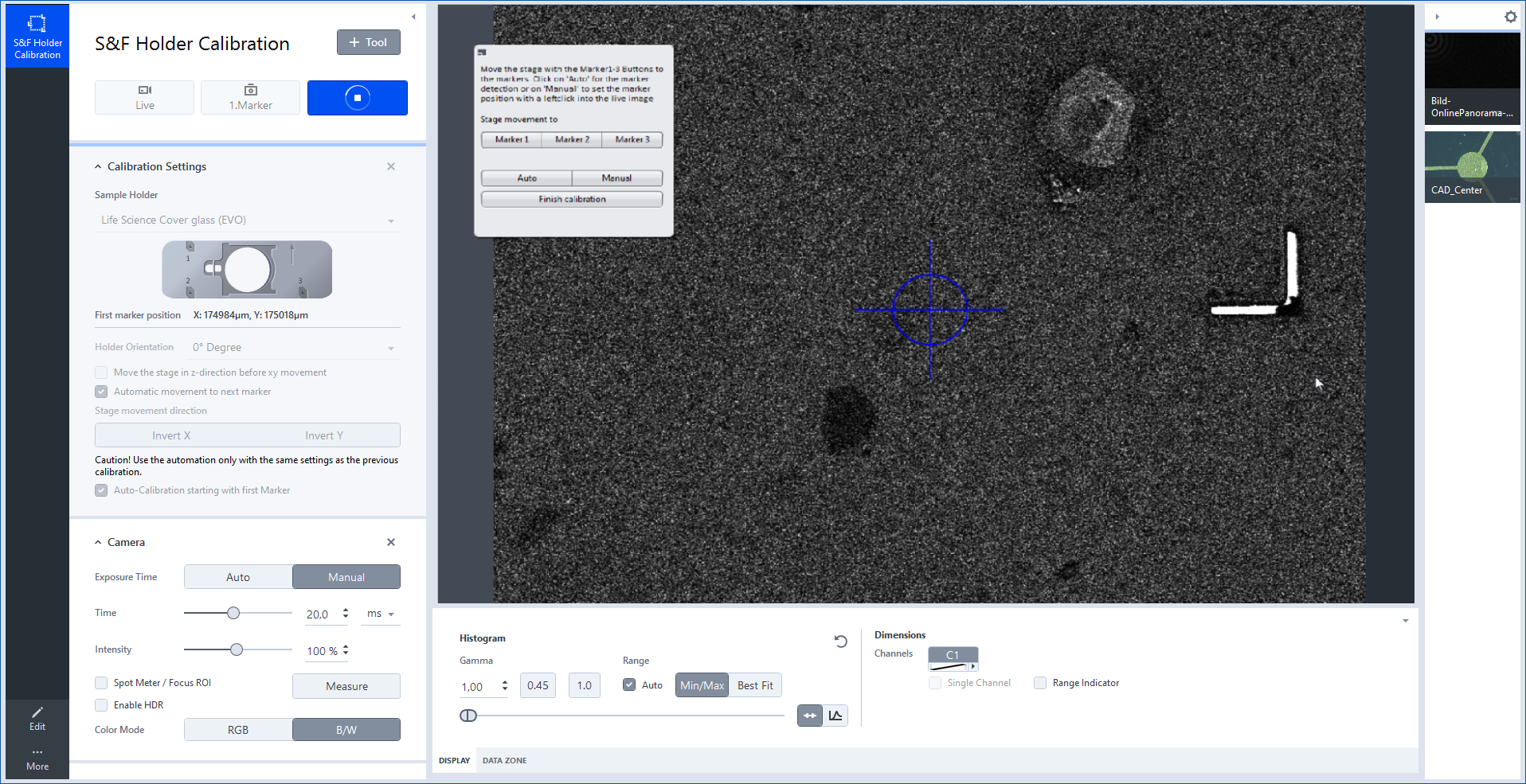
Before you can start to acquire S&F images you first have to calibrate the correlative holder. Note that holder calibration must be performed on both systems (LM and SEM). During calibration the exact positions of the three small fiducial L-shaped markers must be detected (or set manually). For each marker you can decide if you want to use the automatic marker detection or if you want to manually set the marker position, e.g. if the auto detection failed. Since the auto detection usually works fine, we recommend always using it.
- You have inserted the holder to be calibrated on the stage (example LM system).
- Open the S&F Holder Calibration workbench.
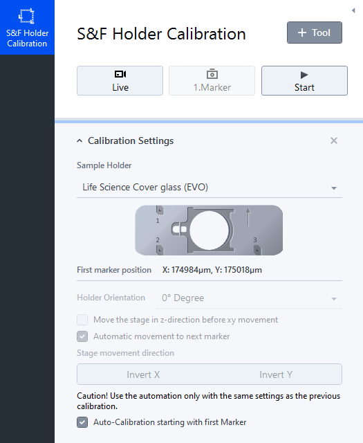
- In the Calibration Settings select the corresponding holder from the drop-down list.
Make sure that the Holder Orientation setting within the software is the same like on the stage. If this is not the case, change the orientation in the software. We also recommend to activate Automatic movement to next marker, so the process will be more fluent. - Click Start on top of the workbench.
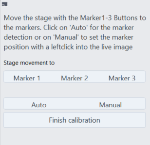
- A dialog will appear to choose whether you want to perform automatic or manual marker detection. We recommend to use the automatic marker detection which is performed as follows:
- Move the stage in the area of the first marker and click Auto . Make sure that the Live image is in focus and the marker is visible.
- The software will now try to detect the first marker on the inserted holder. The marker is detected correctly, when the red crosshair matches the corner of the smaller L-shaped marker exactly. After the detection a confirmation dialog will appear.
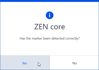
- Click Yes, if the marker was detected correctly.
If the marker was not detected correctly, click No and select Manual mode. Set the marker manually by left clicking with mouse on the outer corner of the small L shaped marker. The position will be saved and you can continue to the next marker.
Repeat the last two steps for the next 2 markers. The dialog box will always show you which marker is to be detected. - If all three markers were detected correctly, the calibration is completed.
- Click Finish Calibration to close the wizard.
- In the Calibration Settings tool you now will see the position data (X/Y) of the first marker. If the holder was calibrated once, you can always move the stage easily and fast to the first marker position by only clicking 1.Marker on top of the workbench.
- You have calibrated the holder successfully. You can now acquire images of your sample. Note that the calibration process must be performed again, after the holder is transferred (shuttled) to the other system. Otherwise the sample positions (ROIs/POIs) cannot be found automatically.
- After you have completed the "default" calibration procedure once, you can perform an automated calibration, e.g. if you have changed the sample on the calibrated holder. To learn more about the auto-calibration, read the chapter Calibrating the S&F Holder Automatically.
Calibrating the S&F Holder Automatically
If you want to perform the automatic calibration the holder must have been calibrated first by using the default calibration procedure. See Calibrating the S&F Holder. Performing auto-calibration the software tries to detect the exact positions of all three, small fiducial L-shaped markers on the holder automatically. The result of the detection will be presented afterwards. The automatic calibration is the easiest way to repeat the calibration process, e.g. if you have changed the sample on the holder and therefore removed the holder from the stage.
- You have inserted the holder to be calibrated on the stage (example SEM stage).
- Open the S&F Holder Calibration workbench.
- Check if the holder is still selected under Sample Holder.
- Activate Auto-Calibration starting with the first marker.
- The software will now start and try to detect all three positions of the small L-shaped markers.
- After the detection procedure you will see three preview images of the markers. On each image the red crosshair must be in the corner of the L-shaped marker.
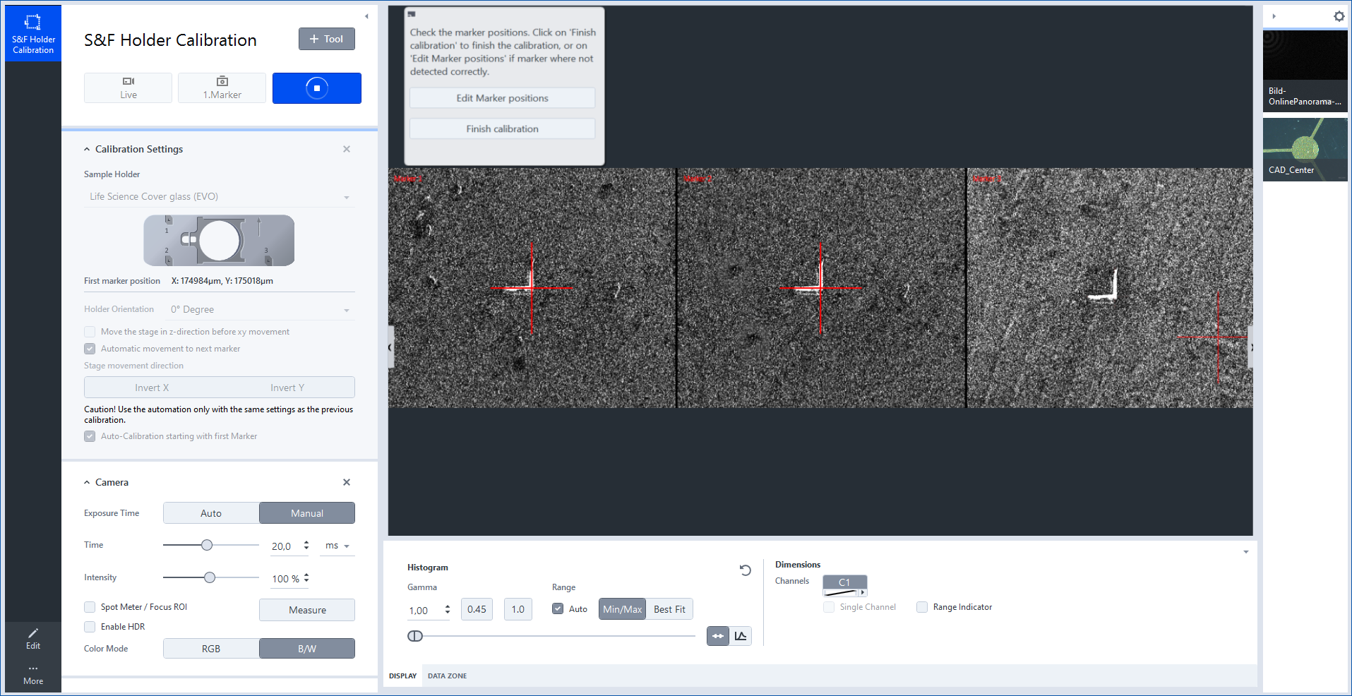
- Click Finish calibration as soon as all three markers were detected correctly.
- If a marker was not detected correctly, click Edit Marker Positions to adjust the position manually.
- You will see a dialog which you can use to navigate to the detected positions and correct them afterwards. In our example Marker 3 was not detected correctly.
- Click Marker 3.
- The stage will move to the position which was not detected correctly.
- Move the stage by the joystick so that the small L-shaped marker is visible in the Live image and click Manual .
- Determine the position manually by left clicking in the corner of the L-shaped marker.
- Click on Finish Calibration. If you want to check if all three markers are detected correctly, you can navigate on the holder by clicking Marker 1-3 buttons.
- You have calibrated the holder successfully. You can now acquire images of your sample. Note the calibration process must be performed again, after the holder is transferred (shuttled) to the other system. Otherwise the same sample positions (ROIs/POIs) cannot be found automatically.
Showing SEM Acquisition Data
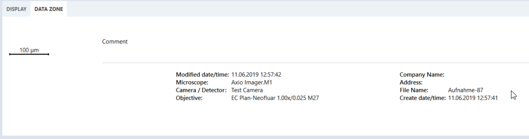
To show SEM acquisition data in the Image Area you can configure the Data Zone tab.
- Click Maintenance > General Options > Documents.
- Select the desired data to be displayed under Optional Data. Up to eight fields can be configured.
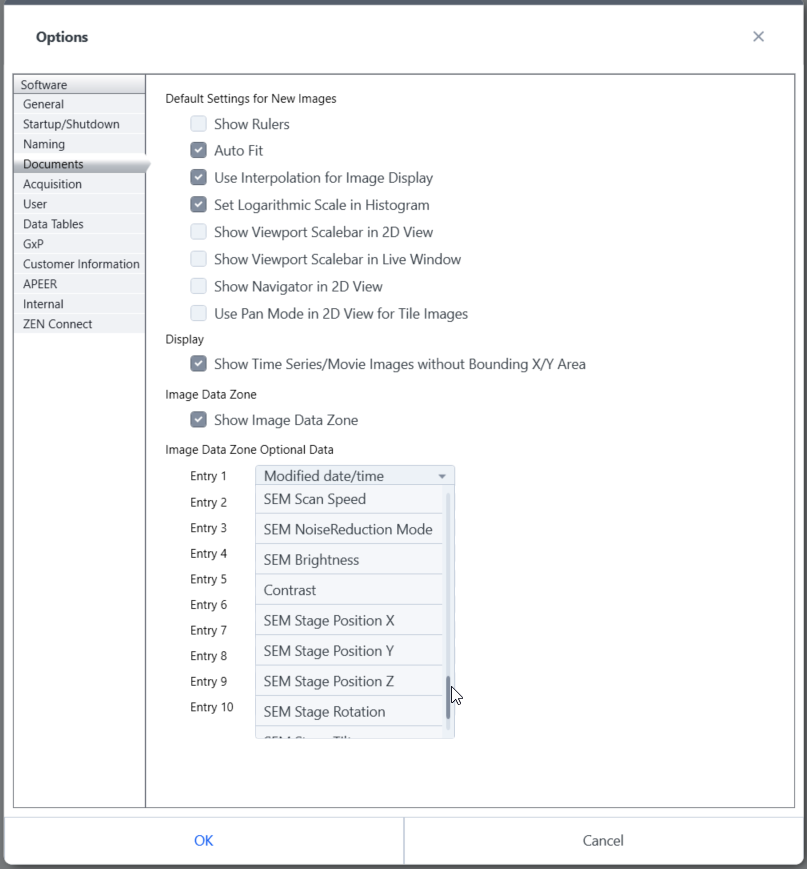
- After an acquisition the fields will be visible in the Data Zone tab.
Correlative Sample Holders
Following ZEISS templates are available:
|
Field of Use |
Holder Template |
|---|---|
|
Life Science |
Life Science Cover glass (EVO) |
|
Life Science Cover glass with fiducials |
|
|
Live Science Cover glass |
|
|
Life Science TEM grid |
|
|
Material Science |
MAT Flat samples 1a, 2a, 3a |
|
MAT Flat samples |
|
|
MAT Geo Slides |
|
|
MAT Particle 47 mm |
|
|
MAT Particle 50 mm |
|
|
MAT Universal A |
|
|
MAT Universal B (A-B) 1a, 2a, 3a |
|
|
MAT Universal B (A-B) |
|
|
MAT Universal B (C-D) 1a, 2a, 3a |
|
|
MAT Universal B (C-D) |
Tips to Ensure Accuracy
On the light microscope
- To ensure good calibration, the objectives must be correctly calibrated.
- We recommend 20x magnification for the automatic marker detection.
- Due to potential objective shift, accuracy will be higher if you acquire images using the same objective that you used for calibration.
On the electron microscope
- The SE2 detector is well suited for marker detection.
- Switch off the beam shift and scan rotation.
- The "Stage only" setting should also be activated under Center Point or Feature.
- Use the stage backlash to increase the stage’s accuracy in locating positions.
General Points
- For images on a SEM use conductible samples.
- Initialize the stages before using Shuttle & Find.
- Calibrate again each time the holder has been inserted into a microscope.
- If the marker is a little dirty, it can be helpful for detection purposes to de-focus it slightly.
- In the case of stitched tiles images accuracy is reduced.