Image Analysis Wizard
This wizard guides you through the setup of an image analysis. The following basic controls enable you to move through the steps:
|
Parameter |
Description |
|---|---|
|
Next |
Moves on to the next step of the wizard. |
|
Back |
Moves back to the previous step of the wizard. |
|
Cancel |
Cancels the wizard. No changes are applied to your settings. |
|
Finish |
Saves the setup and the changes based on your progress and closes the wizard. |
Classes
Difference in Job Mode
The available functionality of the individual steps can differ between the wizard in Free Mode and the steps that can be added in Job Mode, e.g. the Interactive checkbox is not visible in Job Mode.
In this step you can define the classes into which the measured objects in the image are divided.
|
Parameter |
Description |
|
|---|---|---|
|
Interactive |
Activated: The measurement frame definition can be changed interactively while the analysis setting is run. |
|
|
Class List |
Displays the defined classes. If you create a new analysis setting, a predefined set of classes is created automatically. Each class also contains a summation class (not displayed in the class list). Each class contains the individual regions belonging to that class and in the class result table the defined measurement features for each individual object are displayed. The summation class on the other hand concerns all the objects belonging to the class. The corresponding result table contains "statistical" features such as the object count or the mean intensity of all objects belonging to the class. |
|
|
Add Class |
Adds a new individual class to the list on the base level. |
|
|
Add Subclass |
Adds a new subclass to the selected class. |
|
|
Remove Class |
Deletes the selected class from the list. |
|
|
Name |
Defines the name for the selected class in the list. Note that you must not use the name Root for one of your classes as this a reserved keyword. |
|
|
Channel |
Selects the channel that is used for image segmentation of the selected class in the class list. |
|
|
Object Color |
Selects a color to mark the objects of a class. |
|
|
– |
Random |
The objects found by the analysis will be colorized randomly. |
|
– |
Fixed |
Selects the fixed color to mark the objects of a class. |
Frame
Difference in Job Mode
The available functionality of the individual steps can differ between the wizard in Free Mode and the steps that can be added in Job Mode, e.g. the Interactive checkbox is not visible in Job Mode.
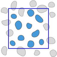
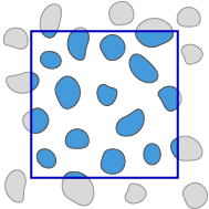
In this step you can define one or more measurement frames. Only the area within the measurement frames gets analyzed. You can also define how the analysis treats objects that are cut by the border of the image or the frame.
|
Parameter |
Description |
|
|---|---|---|
|
Interactive |
Activated: The measurement frame definition can be changed interactively while the analysis setting is run. |
|
|
|
Enables you to select already created measurement frames. To select a measurement frame, click inside it. To select several measurement frames, press Ctrl and click inside the desired measurement frames. Once you have selected a measurement frame, you can change its size. |
|
|
Draw Rectangle |
Enables you to create a rectangle as a measurement frame in the current image. |
|
|
Draw Circle |
Enables you to create a circle as a measurement frame in the current image. |
|
|
Draw Contour (Polygon) |
Enables you to create a contour as a measurement frame in the current image. |
|
|
Remove All Frames |
Removes all drawn-in measurement frames in the current image. To delete single frames, select them and press Del. |
|
|
Maximize Circle |
Activated: Maximizes the drawn-in circle to the full image size. In the case of rectangular images the circle is adjusted to the shorter side. |
|
|
Center Circle |
Activated: Centers the drawn-in circle to the full images size. |
|
|
Mode |
Selects how the measurement frame should be applied. Note that this behavior is only applied when running the analysis (interactively) and not during the setup. The setup always uses the Cut at Frame mode. The following modes are available: |
|
|
– |
Inside Only |
Measures only those objects, that are lying completely within the measurement frame. Objects that are touching the frame or are intersected by the frame are not analyzed.
|
|
– |
Cut at Frame |
Measures all objects that are lying within the measurement frame. Objects that are intersected by the measurement frame are measured precisely up to the measurement frame.
|
|
Left |
Sets the starting point for the frame on the X axis in pixels. |
|
|
Top |
Sets the starting point for the frame on the Y axis in pixels. |
|
|
Width |
Sets the width of the frame in pixels. |
|
|
Height |
Sets the height of the frame in pixels. |
|
|
Color |
Selects the color of the frame. |
|
|
Show Frame On Analyzed Image |
Activated: Displays the frame on the image after the analysis has run. |
|

Interactive Segmentation
Difference in Job Mode
The available functionality of the individual steps can differ between the wizard in Free Mode and the steps that can be added in Job Mode, e.g. the Interactive checkbox is not visible in Job Mode.
In this step you can post-process the segmented objects interactively. You can modify the results of the automated segmentation when you analyze your image data. Note that during the setup of the analysis (via Setup Image Analysis in Free Mode), the segmentation is only performed on the area visible in the viewport. If you enter the interactive analysis or are in Job Mode, the image will be fully segmented.
|
Parameter |
Description |
|
|---|---|---|
|
Interactive |
Not available for Technical Cleanliness Analysis. |
|
|
Class List |
Not available for Technical Cleanliness Analysis. |
|
Edit Region section
|
Parameter |
Description |
|---|---|
|
Draw |
Enables you to draw new objects of the selected class. |
|
Erase |
Enables you to erase parts of an object. While pressing the left mouse button, outline the parts of the object that you want to erase. Right-click to erase these parts of the object. |
|
Cut |
Enables you to separate connected objects. While pressing the left mouse button, draw in the separation line between the objects. Right-click to cut the objects. |
|
Merge |
Enables you to connect objects. While pressing the left mouse button, outline the parts of the object that you want to merge. Right-click to merge the objects. |
|
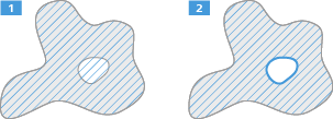
Fill |
Fills a hole. To fill a hole, left-click on the hole. If a selected object completely surrounds another potential area, then the enclosed area is also included (
|
|
Remove |
Enables you to remove a drawn in object by clicking on it. |
|
Remove All |
Deletes all drawn objects. |
|
Draw Rectangle |
Enables you to add a rectangular object or cut a rectangular region from an object. |
|
Draw Circle |
Enables you to add a circular object or cut a circular region from an object. |
|
Draw Contour |
Enables you to add an object or cut a region from an object. |
|
Draw Contour (Spline) |
Enables you to add an object or cut a region from an object. |
|
Draw Active Contour |
Enables you to add an object or cut a region from an object. |
|
Draw Polyline Region |
Enables you to add a line-object. |
|
Draw Point |
Enables you to add a point object. |
 ).
).
Region Growing section
For the module Technical Cleanliness Analysis, only Undo and Redo are available.
|
Parameter |
Description |
|
|---|---|---|
|
Mode |
Expands or reduces the size of an object based on the brightness of surrounding pixels |
|
|
– |
+ |
Click on areas in the image you want to add to the selected object class. |
|
– |
- |
Click on areas in the image you want to remove from the selected object class. |
|
Intensity |
Sets the tolerance value for the intensity. The tolerance value specifies how much the intensity of a pixel may deviate from the average intensity of the selected object in order to still "grow" to become part of the object. A higher value means that more pixel values similar to the selected one are included. A lower value means that only the exact pixel value selected is included. |
|
|
Color |
Only active if your input image is a color image. |
|
|
Fill |
Fills holes that are created during region growing. Activated (
|
|
|
Undo |
Undoes the last action. |
|
|
Redo |
Restores the last undone action. |
|
 ): Only the detected object is included.
Post Processing section
Only visible for images with a size smaller than 10000 x 10000 pixel.
|
Parameter |
Description |
|---|---|
|
Region Filter |
Reapplies the region filter you defined in the previous step to the post-processed image. |
Results Preview
In this step you see a preview of the measurement results. The results table contains only the measurements performed in the current view port. These results may differ from the actual results when the complete image analysis is performed. This increases the performance during the setup.
The results in the table depend on the settings you made in the Feature step. The table contains all selected features for the highlighted class/classes. Click on a row of the table to highlight the corresponding object in the image or vice versa.
The following controls are only available in Free Mode:
|
Parameter |
Description |
|
|---|---|---|
|
Class List |
Select the class for which you want to see the measured features. |
|
|
Highlight Box |
||
|
- |
Color |
Sets the color of the highlight box surrounding the selected object in the image. |
|
- |
Line Width |
Sets the line width of the highlight box around the selected object in the image. |