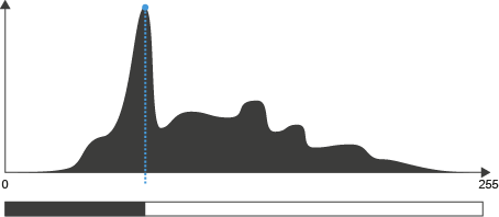
Segmentation Group
Canny Tool
This tool detects edges in a gray scale image using the Canny algorithm, which is the most common, general-purpose edge detection algorithm. The tool enables you to specify how strong the input image is smoothed before edge detection is performed.
|
Parameter |
Description |
|---|---|
|
Sigma |
Specifies the extent of smoothing applied to the input image before the edges are detected. Smoothing reduces noise and thus the chance of obtaining false edges. |
|
Threshold |
Specifies the steepness an edge must possess to be recognized by the tool. The steepness is the rate at which the gray values change from bright to dark or vice versa.
|
Marr Tool
This tool detects edges or regions in an image using the Marr–Hildreth algorithm, which smooths the image using a Gauss filter and then applies a Laplace filter to the smoothed image. The result is a measure for the second derivative of the image brightness at each position. Zero crossings of this second derivative are detected to obtain the edges.
Due to its detection method this tool is very sensitive to any change in image intensity. It is thus prone to detecting false edges, i.e. to detect noise or slight local changes in brightness as edges. Compared to other edge detectors, you might need to apply a larger amount of smoothing to obtain satisfying results.
You can display either the detected edges or the regions enclosed by the edges.
|
Parameter |
Description |
|
|---|---|---|
|
Sigma |
Specifies the extent of smoothing applied to the input image before the edges or regions are detected. Smoothing reduces noise and thus the chance of obtaining false edges. |
|
|
Display Mode |
Specifies how the results are displayed: |
|
|
– |
Edges |
The edges around regions of bright pixels are displayed as thin white lines, all other pixels are displayed black. |
|
– |
Regions |
The regions of bright pixels are displayed white, the edges and the space between the bright regions are displayed black. |
Threshold Tool
This tool splits the image into foreground and background areas. Pixels within a specified range are considered foreground pixels and are not modified. All other pixels are considered background pixels and set to black. You can use an automatic method to determine the range or you can specify it manually. If the input image is a color image, you can set the brightness ranges for each color channel separately.
Automatic range
|
Parameter |
Description |
|
|---|---|---|
|
Method |
Specifies the algorithm used to automatically detect the threshold boundaries. The most suitable algorithm depends on your precise requirements. The value also depends on the bit depth of the image. |
|
|
– |
Otsu |
The pixel values below the threshold are designated as background and those above the threshold as foreground. It iterates through all possible threshold values and for each value calculates the spread of the pixel intensities of the background and foreground pixels. The threshold is set at the value that minimizes both spreads. This method is particularly suited to light objects on a dark background. |
|
– |
Maximum Peak |
The threshold is set to the pixel value that occurs most frequently.
|
|
– |
Iso Data |
The pixel values below the threshold are designated as background and those above the threshold as foreground. An initial threshold value is chosen, and the mean pixel intensity of the foreground and background pixels is calculated. These two mean values are averaged and the result serves as the input threshold for the next calculation. The process is repeated until the threshold value no longer changes.
|
|
– |
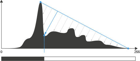
Triangle Threshold |
The algorithm constructs a line between the peak of the highest frequency pixel intensity and the lowest pixel intensity. The distance between the line and the histogram is computed for all values along the line. The pixel intensity where the line is longest is used as the threshold. This method is particularly suited when the foreground pixels only have a weak peak in the histogram.
|
|
– |
Three Sigma Threshold |
The pixel value that occurs most frequently is calculated. The standard deviation of the values in the peak is calculated. The threshold is set to the pixel intensity that is the sum of the peak value and three times the standard deviation. |
Manual range
|
Parameter |
Description |
|---|---|
|
Level Low, Level High |
Specifies the lower and upper boundaries of the brightness range. All pixels with gray values outside the brightness range are considered to be background pixels and changed to black. If the input image is a color image, you can specify the boundaries for each color channel separately. |
|
Create Binary |
|
|
Invert Result |
Reverts the way the pixels are treated.
|
Threshold Auto Tool
This tool splits the image into foreground and background areas. Pixels within a specified range are considered foreground pixels and are not modified. All other pixels are considered background pixels and set to black. The brightness range is determined by an automatic method.
Automatic range
|
Parameter |
Description |
|
|---|---|---|
|
Method |
Specifies the algorithm used to automatically detect the threshold boundaries. The most suitable algorithm depends on your precise requirements. The value also depends on the bit depth of the image. |
|
|
– |
Otsu |
The pixel values below the threshold are designated as background and those above the threshold as foreground. It iterates through all possible threshold values and for each value calculates the spread of the pixel intensities of the background and foreground pixels. The threshold is set at the value that minimizes both spreads. This method is particularly suited to light objects on a dark background. |
|
– |
Maximum Peak |
The threshold is set to the pixel value that occurs most frequently.
|
|
– |
Iso Data |
The pixel values below the threshold are designated as background and those above the threshold as foreground. An initial threshold value is chosen, and the mean pixel intensity of the foreground and background pixels is calculated. These two mean values are averaged and the result serves as the input threshold for the next calculation. The process is repeated until the threshold value no longer changes.
|
|
– |
Triangle Threshold |
The algorithm constructs a line between the peak of the highest frequency pixel intensity and the lowest pixel intensity. The distance between the line and the histogram is computed for all values along the line. The pixel intensity where the line is longest is used as the threshold. This method is particularly suited when the foreground pixels only have a weak peak in the histogram.
|
|
– |
Three Sigma Threshold |
The pixel value that occurs most frequently is calculated. The standard deviation of the values in the peak is calculated. The threshold is set to the pixel intensity that is the sum of the peak value and three times the standard deviation. |
Manual range
|
Parameter |
Description |
|---|---|
|
Create Binary |
|
|
Invert Result |
Reverts the way the pixels are treated
|
Threshold Dynamic Tool
This tool splits the image into foreground and background pixels by performing an adaptive gray value segmentation. It is particularly suited to the segmentation of small structures on a varying background.
The tool initially applies a low-pass filter and then subtracts this low-pass-filtered image from the input image. The effect largely depends on the size of the filter matrix (Kernel Size).
|
Parameter |
Description |
|---|---|
|
Kernel Size |
Specifies the matrix size of the low pass filter in X and Y direction symmetrically around the pixel currently processed and determines the extent of the smoothing effect. Set a low Kernel Size value to segment small regions or regions with low gray value contrast from the background. Set a higher Kernel Size value to segment larger regions from the background. As the affected pixel is at the center, the edge length of the filter matrix is always an odd number. If you enter an even number via the keyboard, the value is always set to the next highest odd number. |
|
Threshold |
Defines the difference in brightness between the regions to be detected and the background. Segmented pixels are set to the maximum gray value (white), other pixels are set to zero (black). |
|
Create Binary |
|
|
Invert Result |
Reverts the way the pixels are treated.
|
Valleys Tool
This tool detects lines of dark pixels (valleys composed of low gray values) on a bright background. In the output image, the detected lines are displayed white on a uniform black background.
|
Parameter |
Description |
|---|---|
|
Sigma |
Specifies the extent of smoothing applied to the input image before the lines of dark pixels are detected.
|
|
Threshold |
Specifies the steepness a valley must possess to be recognized by the tool. The steepness is the rate at which the gray values increase starting from the bottom of a valley.
|