Non-Metallic Inclusion Analysis (NMI)
This module enables you to evaluate and rate non-metallic inclusions in steel (Oxides, Sulfides and Nitrides). The following standards are supported: ASTM E45, ISO 4967, JIS G0555, GB/T 10561, EN 10247, SEP 1571 und DIN 50602.
Overview
NMI Analysis (Non-Metallic Inclusion Analysis) is a module for fast inspection and evaluation of steel cleanliness. You can use it to detect and analyze steel impurities like non-metallic inclusions originating from the production process. The module is a standard based, automated workflow solution for specimen acquisition, inclusion classification, inclusion rating, result documentation and archiving. It offers interactive result views for reliable inclusion inspection and revision. Therefore it is part of a dedicated system solution focused on efficient steel cleanliness analysis and consisting of a microscope, motorized scanning stage, digital camera, high-end workstation. The module is used for quality control of steel products.
The NMI Analysis module further supports you analyzing the steel cleanliness of your products. It uses different standards with methods calculating the inclusion content based on standard templates which can be adapted in the standard template editor. The result is a set of standard specific characteristic values describing the steel cleanliness per inclusion type. The result is presented in the report evaluation document. The module displays for each selected standard the global results with an overview of detected oxides, sulfides and nitrides as well as artifacts.
In the next step, you can perform a detailed inspection of the complete specimen using a grid of standard measuring fields.
Comparison of Standards
The following table gives a brief overview of methods K and M concerning SEP 1571 and comparable standards.
|
SEP 1571 |
DIN EN 10247 |
ISO 4967 |
ASTM E45: |
DIN 50602 |
|---|---|---|---|---|
|
Results cannot be influenced by change of category (thin/heavy) |
Results cannot be influenced by change of category (thin/heavy) |
Shifting of marginal thin (thin) inclusions towards thick (heavy) is possible |
Shifting of marginal thin (thin) inclusions towards thick (heavy) is possible |
Results cannot be influenced by change of category (thin/heavy) |
|
Free path proximity conditions in and transverse to the rolling direction |
Free path proximity conditions in and transverse to the rolling direction |
Free path proximity conditions in and transverse to the rolling direction |
Distance 40 μm in rolling direction and 15 μm transverse to them, likely similar to ISO 4967. |
Proximity condition relative to the inclusion size; direction of distance is undefined |
|
Definition of a smallest particle for forming lines of 5 μm² |
Smallest particle 2 μm x 3 μm |
Not available |
According to chapter 11.4 inclusions thinner than 2 μm are not considered in the degree of severity. |
Not available |
|
Globular when l/b < 2.0 |
Globular when l/w < 3.0 |
Globular when l/b < 3.0 |
Globular when l/b < 2.0 |
Globular is not defined |
|
No evaluation limits (g < 0, g > 9 possible) |
Evaluation range is limited, optionally expandable upwards |
Evaluation range is unlimited upwards (Annex D1) |
Evaluation range is expandable upwards (> 3) |
Restricted evaluation limits from K0 to K9 |
|
Uniform evaluation criteria for all inclusion types: surface |
Uniform evaluation criteria for all inclusion types: surface area or length or number |
Different evaluation depending on the inclusion type (length, thickness, number) |
Different evaluation depending on the inclusion type (length, thickness, number) |
Uniform evaluation criteria for all inclusion types: surface |
|
Oversized (not classifiable) types are not available, since an extension of the class limits is possible |
Oversized is possible, in current revision without a defined measure (In the revision of 2017 the following applies: Oversized only for excess lengths: they have to be evaluated as the next lower class and noted separately.) |
Oversized is possible, separately noted |
Oversized is possible, separately noted outside of the standard value table |
Oversized are considered as macro-inclusions |
Concept
With the operating concept of the NMI Analysis module, pre-defined measurement workflows are adapted by the supervisor for the every day routine of the operator. The performance of a measurement can be automated to such an extent that only the project data need to be entered and the entire analysis process can run almost automatically. Due to these automated workflows, the operator influence on the measurement results can be reduced to a minimum. In addition to the quality gained, the time necessary for the measurement is reduced as well. Supervisors and operators can focus on their specific tasks.
The operation of the module is based on the following operating concept:
- Modifying and Managing Job Templates (Supervisor)
- Copy and edit pre-configured NMI job templates in order to adapt the workflow to your needs and to the operator routine task, manage job templates, inspect and approve job results. Note that under Job Mode you find pre-defined job templates for non-metallic inclusion assessment according to the standards. For more information, see Introduction to Standards.
- Running Job templates (Operator)
- Run NMI job templates created by the supervisor. Inspect und revise results if required using the results views.
- Optional: Modifying and managing standard templates (Supervisor)
- Copy and edit pre-configured standard templates in order to adapt the standard according to company internal guidelines for non-metallic inclusion assessment. Standard adaption might be also beneficial for NMI analysis of non-steel metals. Define individual parameters for minimum particle size, shape determination (globular & elongated), next neighbor relationships, and for inclusion formation.
- Note that under Manage Templates you can edit the find pre-configured standard templates: one per standard and method.
- For more information, see Standard Template Editor. For more information regarding available standards, see Introduction to Standards.
- Note that for the initial operations you must select in the Standard Selection workbench (in the first step of your job template), the desired standard templates.
Note: In the role of a supervisor it is possible to perform functionalities of the operator.
General Workflow preparations
A pre-defined job template is included in the software, when you have licenced the NMI Analysis module. In this documentation, we will explain the procedure according to the existing, pre-defined job templates. The following job templates are available by default:
|
Parameter |
Description |
|---|---|
|
Non-Metallic Inclusion Analysis |
You load or acquire the images of specimen with oxides and sulfides, and analyze them. |
|
Non-Metallic Inclusion Analysis Nitrides |
You load or acquire the images of specimen with oxides, sulfides and nitrides and analyze them. |
As a Supervisor, you can access/edit the job template under Job Mode. On the left side, in the Categories list under Material Analysis, select NMI Analysis.
In the templates list, you see the available job template. When you double-click on the entry in the list, the corresponding job template opens. The job templates generally contain four major tasks:
- Filling out an Input Form
- In this step, the operator has to fill out the input form with user and specimen specific information, etc.
- Image Acquisition
- Image acquisition of the pre-defined specimen area.
- Performing the Analysis
- In this step particles are extracted by image segmentation and inclusions are grouped according to the selected standards. The detailed workflow is described in the following sections.
- Creating a Report
- After the analysis, reports are generated containing the job results with characteristic values according to the selected standards. One report per specimen and one report displaying the summary statistic of all acquired images of the specimen per standard.
Operator Workflow
In general, the evaluation of steel cleanliness consists of the following steps.
- Sampling and specimen preparation
Sectioning, hardening, grinding, mounting (not mandatory), and several polishing steps are performed. Usually, n-representative locations of one lot are cut out. The specimen size and the location are dependent on the steel product to be analyzed. Note that the polished surface must be parallel to the main deformation direction, otherwise the generated measurement results are not meaningful. - Specimen acquisition and analysis
Images of the prepared steel specimen are acquired, usually six test objects, originating from one lot. The inclusions are classified by size and type. Inclusions are rated based on standard specific test methods, usually several standards with the corresponding methods are applied.
Note: The main deformation direction must be considered for a correct placement of the individual specimen on the microscope stage. In doing so, the elongated inclusions are oriented either horizontal or vertical related to the x-axis of the stage. Otherwise the generated measurement results are not meaningful. - Inspection and documentation of results
General Workflow of the Operator
|
Step |
Operator task |
|---|---|
|
1 |
Place specimen (often up to six) on the scanning stage of the microscope using a stage insert with a steel specimen holder. |
|
2 |
Select job template for NMI Analysis and executes job. |
|
3 |
Fill in data in the overarching and specimen form. |
|
4 |
Optional: Adjust acquisition pre-settings. |
|
6 |
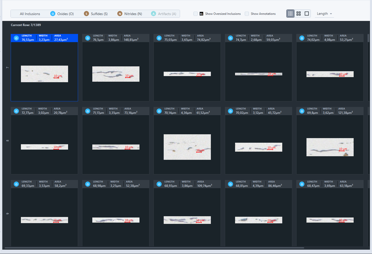
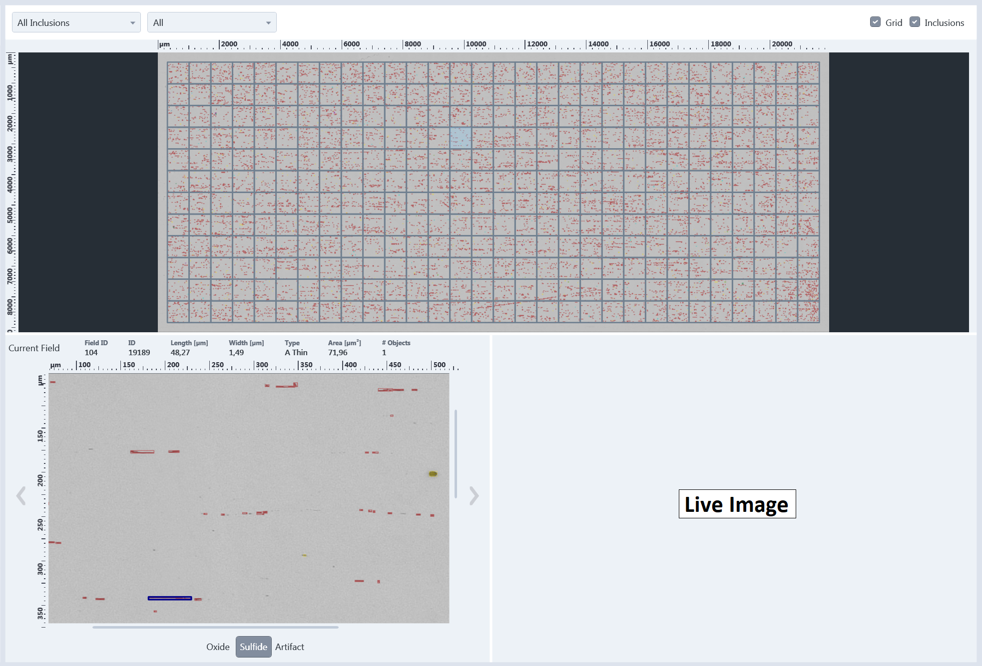
Inspect the results using the interactive result views and the report document view. |
|
7 |
Optional: Modify results using the interactive views, (Global Result view and Field Based Inspection), i.e. changing the inclusion type or excluding artifacts. |
|
8 |
Perform the final inspection of the test methods results in the Report view. |
|
9 |
Optional: Re-open and/or export job results via Browse Job Results. |
Best Practice
General remarks for image acquisition:
- Perform specimen acquisition in brightfield contrast, usually with a total magnification of 100x.
- Acquire specimen with oxides and sulfides in BW mode. Appropriate job template: Non-Metallic Inclusion Analysis.
- For nitrides, the image must be acquired in color mode. Appropriate job template: Non-Metallic Inclusion Analysis Nitrides.
- Adjust image brightness and exposure time so that also the light gray inclusions are well contrasted.
Best practice for manual thresholding setting (segmentation)
- Use the auto threshold as base setting.
- Select a specimen area which shows both Oxides and Sulfides.
- Zoom in using the mouse wheel until finer grey inclusions are clearly visible.
- Adjust the Tolerance Upper Sulfide Threshold to avoid artifacts from potential matrix background detection.
- Toggle with Oxide, Sulfide and All buttons to inspect the segmentation result; this at various positions.
If the result of thresholding is as expected, no further action is needed, otherwise adjust the thresholds for oxides and sulfides manually.
The upper threshold value for the oxides determines automatically the lower threshold value for sulfides.
For this purpose, start adjusting the oxide threshold range and continue afterwards with setting of the upper sulfide threshold value. Fine tuning of the segmentation results is possible with the Tolerance Sulfide Range.
For more information, see Basics of Running a Job.
Supervisor Workflow
The NMI Analysis module offers different degrees of automation. It depends on the experience of the operator and the type of specimen, to which degree the workflow should be automated. In the role of the Supervisor, you create the workflows for the Operators based on pre-defined job templates in Job Mode. In general, the Supervisor modifies the degree of automation using following two options: Firstly, the Supervisor can set a task to Run Silent, i.e. the selected working step is performed but not visible to the Operator. The results of silent steps are saved as well in the archive. Secondly, the Supervisor can define which part of the tool shall be visible to the Operator.
General Workflow of the Supervisor
|
Step |
Supervisor task |
|---|---|
|
1 |
Select standards relevant for specimen analysis. Optional:
|
|
2 |
Configure default specimen acquisition settings. For more information, see section Best practice for image acquisition below. |
|
3 |
Adjust delineation and if required segmentation settings. Default: Auto Segmentation For more information, see section Best practice acquisition & threshold setting below. Optional:
System:
|
Best Practice for image acquisition
General remarks for image acquisition:
- Specimen acquisition is performed in brightfield contrast, usually with a total magnification of 100x.
- Specimen with oxides and sulfides shall be acquired in BW mode; appropriate job template: Non-Metallic Inclusion Analysis.
- For nitrides, the image must be acquired in color mode; appropriate job template: Non-Metallic Inclusion Analysis Nitrides.
Initial steps for image acquisition: Adjust exposure time and focus on the specimen surface.
Settings for Light Path Editing tool:
- Configure the microscope hardware and camera settings used for routine NMI Analysis.
- Adjust image brightness and exposure time so that also the light gray inclusions are well contrasted.
- Copy and edit the defined settings.
Settings for the Extended Camera tool:
- Adjust the white balance in case of using the color mode of the camera.
- Perform a shading correction.
- Close the extended camera tool.
Best practice for manual thresholding setting (segmentation)
Manual threshold setting
- Use the auto threshold as base setting.
- Select a specimen area which shows both Oxides and Sulfides.
- Zoom in using the mouse wheel until finer grey inclusions are clearly visible.
- Adjust delineate to make sure that a potential Oxide-halo (a ring of lighter gray values around the border line of oxides) effect is minimized.
- Adjust the Tolerance Sufide Range to avoid artifacts from potential matrix background detection.
- Toggle with Oxide, Sulfide and All buttons to inspect the segmentation result; this at various positions.
If the result of thresholding is as expected no further action is needed, otherwise adjust the thresholds for oxides and sulfides manually.
For this purpose, start adjusting the oxide threshold range and continue afterwards with setting of the upper sulfide threshold value. Fine tuning of the segmentation results is possible with the Tolerance Sulfide Range.
The upper threshold value for the oxides determines automatically the lower threshold value for sulfides.